Continuous Rotation Servo Hack
I needed motors for a small robot and I wanted to keep it simple and inexpensive. Ordinarily you need a DC motor with gearbox and an h-bridge or motor drivers. Lots of parts and assembly. So instead I’m going to use servos to drive the robot!
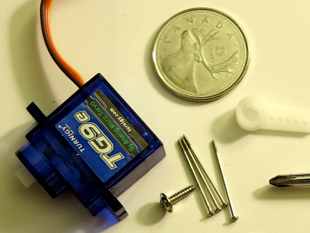
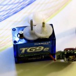
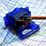
I have Turnigy TG9e, 9g Analog Micro Servos which are compact and inexpensive.
Ordinarily a servo can only turn 180 degrees. You command it to go to some angle between 0 and 180 degrees and the servo attempts to go to that angle. For instance if you “center” the servo by commanding 90 degrees it will go to that position. If you force the servo to stop it from going to that position it will go to that position when you stop forcing. Be careful if you try this as it’s easy to strip the gears on these inexpensive servos.
After this hack, the servo will run continuously instead of only within the 180 degrees. If you command 90 degrees (center) it will do nothing. If you command 0 degrees it will run full speed in one direction continually. If you command 180 degrees it will run the other direction. If you command 95 degrees it will run slower than if you command 100 degrees. The further you command from center the faster it will run.
It’s a fairly easy hack. In summery you set the pot to it’s center, lock it in place, then make adjustments so the output shaft can rotate fully.
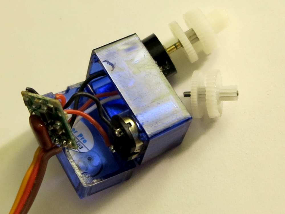
Disassembling Turnigy TG9e
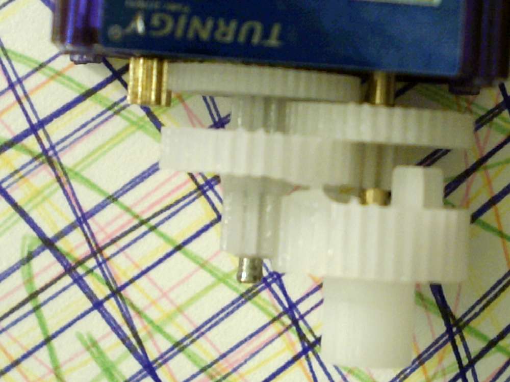
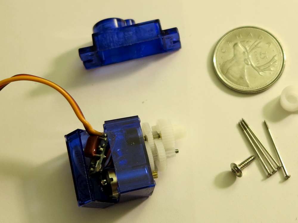
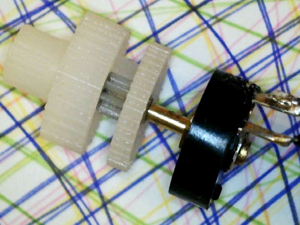
Remove any servo wheel or arm, then remove the four long screws from the bottom. The top pops off exposing gears. The bottom pops off exposing electronics. Removes stickers as necessary. The output shaft is actually pressed onto the pot shaft. As you can see in the right picture below the pot (black) can be pulled out of the top. Once the pot is dangling, you can pull the output gear straight off. It takes a bit of force and care.
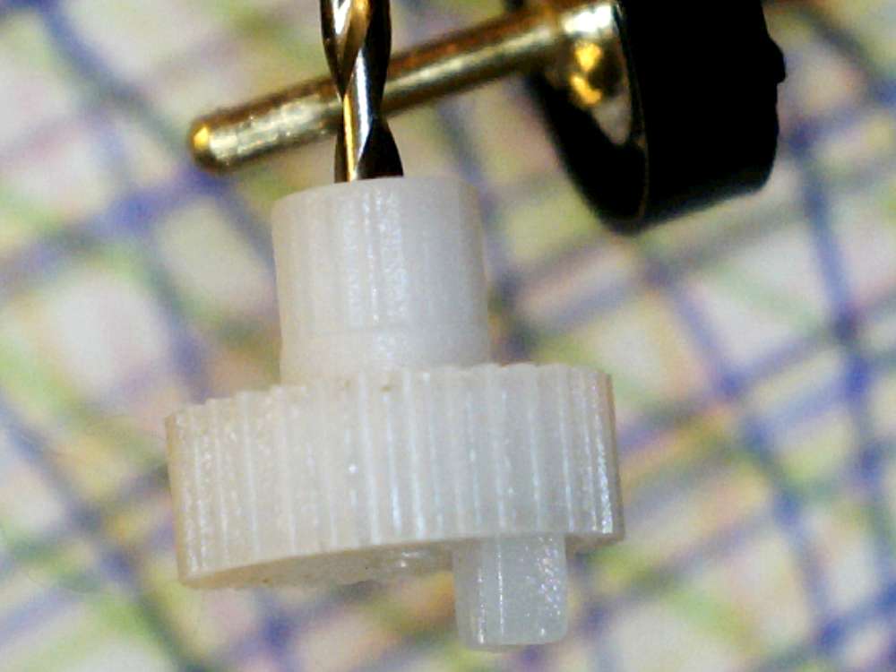
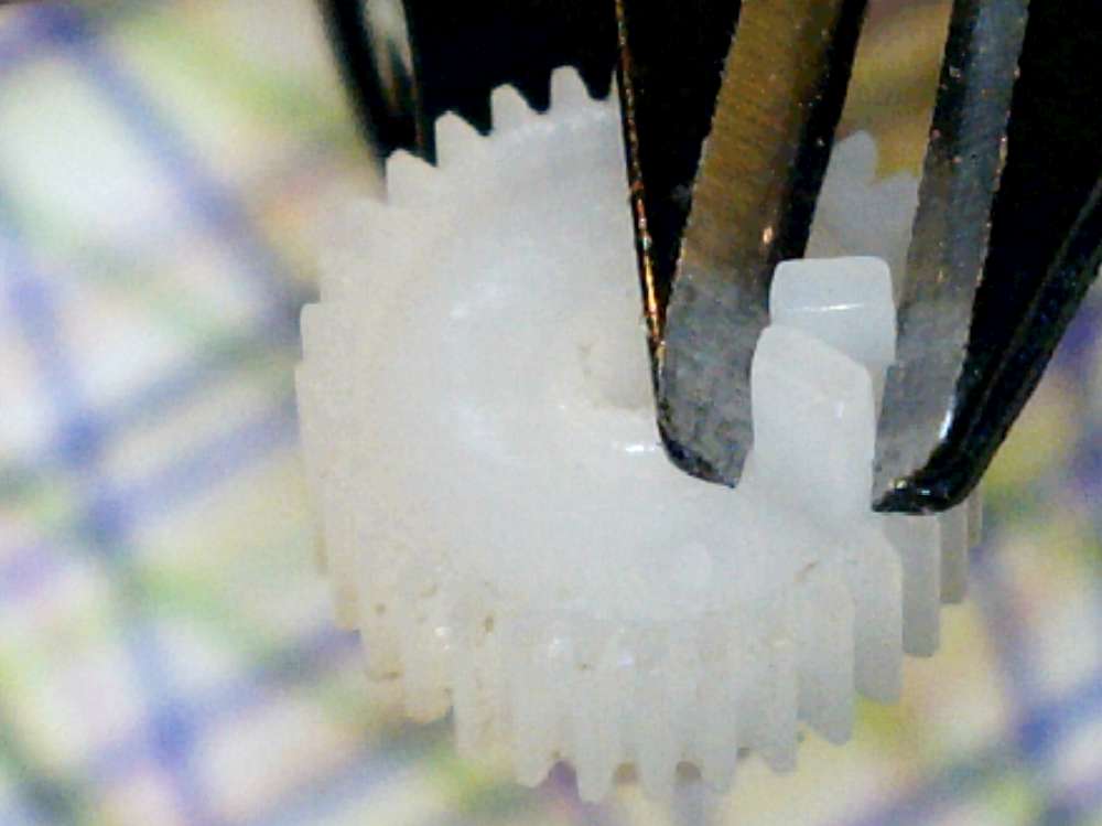
Output Gear
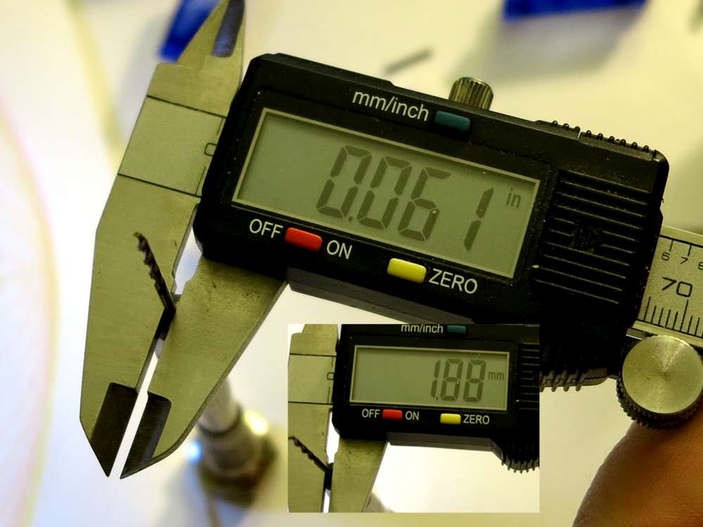
Once you have the output gear off you can drill it so it will rotate on the pot shaft. Also clip off the block which prevents full rotation of the servo. The measurement of the drill bit shown in the picture may be a little large. I was careful to just inert the drill then back it out so we’re not removing very much material.
Lock Pot (Option 1)
This is the easiest way but you ruin the pot.
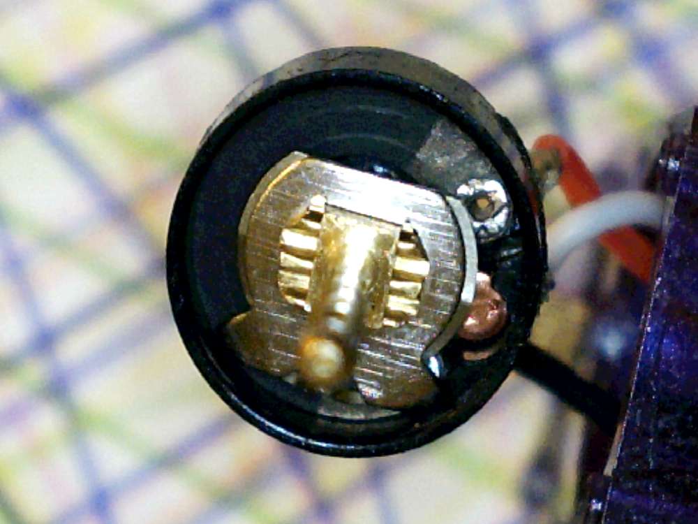
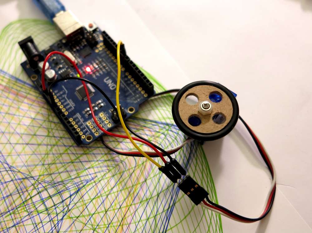
Connect the servo to an Arduino. Dark wire is ground, red is 5V and the yellow/orange bright colored wire is PIN9. Command the servo to go to center (code just below). Then turn the pot till the motor stops running. Squirt glue gun into the pot wiper area to lock the pot. Keep the servo running till the glue sets so you know for sure it has not shifted before setting. The photo at the right above shows the wiper area of the pot where the glue goes. Here’s a brief video describing it.
#include <Servo.h>
Servo myservo;
int pos = 0;
void setup() {
  myservo.attach(9);
}
void loop() {
myservo.write(90);
}
Remove Pot From Circuit (Option 2)
This is a bit more tricky than Option 1 but you don’t necessarily destroy the pot. Ideally you’ll also have well match resistors.
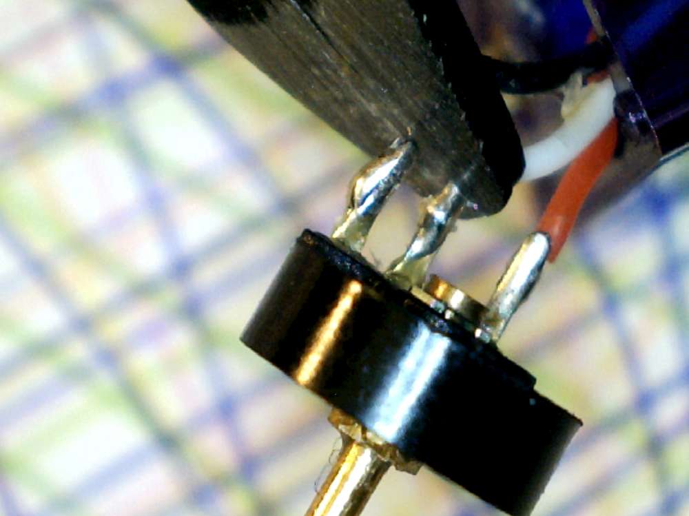
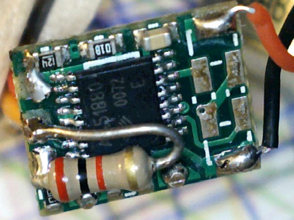
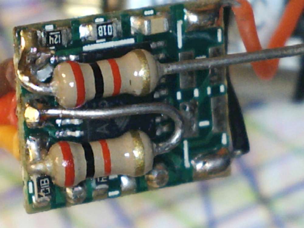
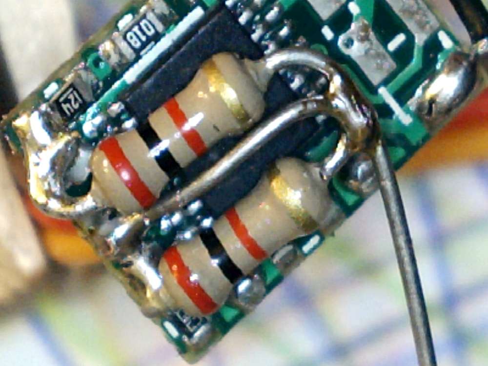
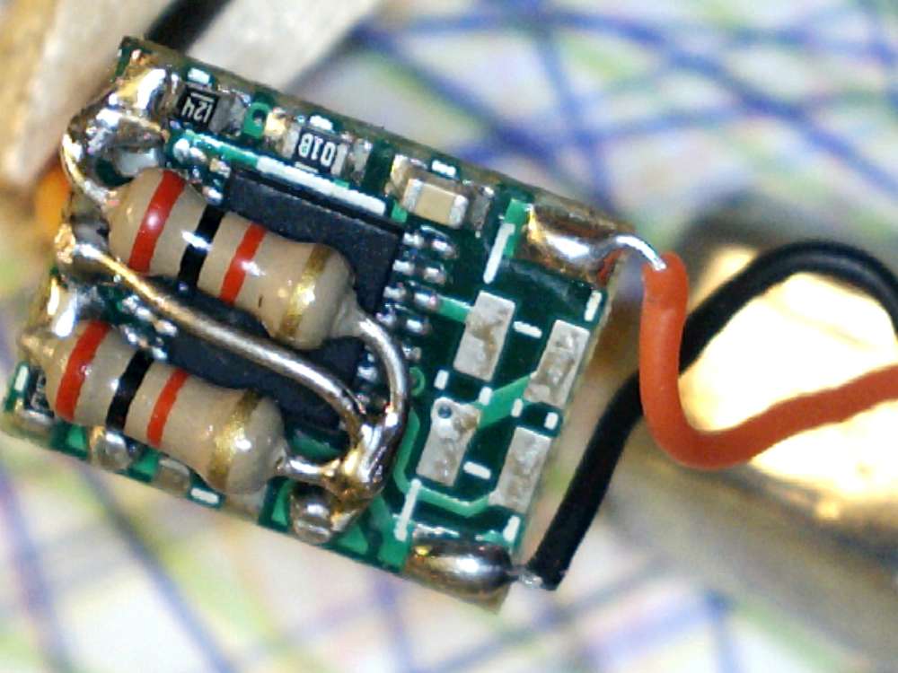
Snip pot wires and unsolder them from the circuit board. So the three pot wires will be completely removed. The three pads on the circuit board where the three wires were is where you will solder two resistors. A resistor from pad A to B and one from B to C.
The pot is around 3.6K so the resistors should be about half that. It works well with 1.5K.
Surface mount is ideal but I didn’t have any on hand…
Reassembly
If you mix up the gears don’t panic. Just place the pot and shaft in their place and the gears go in order of thinnest to thickest. As you can see on the left I have the smallest and second smallest gear. Then I add the third and fourth gear.
The electronics has to get packed in the bottom. I put it in upside down compared to the way it came out. Seems to fit better.

Testing
Once you have the servo back together you can try and run it.
You can run the example program using Arduino by connecting red to 5v, dark to ground and the bright wire to pin 9. Then load the servo sweep from the examples (or use the sketch below).
#include <Servo.h>

Servo myservo;  // create servo object to control a servo
                // twelve servo objects can be created on most boards

int pos = 0;    // variable to store the servo position

void setup()
{
  myservo.attach(9);  // attaches the servo on pin 9 to the servo object
}

void loop()
{
  for(pos = 85; pos <= 95; pos += 1) // goes from 0 degrees to 180 degrees
  {                                  // in steps of 1 degree
    myservo.write(pos);              // tell servo to go to position in variable 'pos'
    delay(700);                       // waits 15ms for the servo to reach the position
  }
  for(pos = 95; pos>=85; pos-=1)     // goes from 180 degrees to 0 degrees
  {
    myservo.write(pos);              // tell servo to go to position in variable 'pos'
    delay(700);                       // waits 15ms for the servo to reach the position
  }

  for(pos = 0; pos <= 180; pos += 1) // goes from 0 degrees to 180 degrees
  {                                  // in steps of 1 degree
    myservo.write(pos);              // tell servo to go to position in variable 'pos'
    delay(20);                       // waits 15ms for the servo to reach the position
  }
  for(pos = 180; pos>=0; pos-=1)     // goes from 180 degrees to 0 degrees
  {
    myservo.write(pos);              // tell servo to go to position in variable 'pos'
    delay(20);                       // waits 15ms for the servo to reach the position
  }

}
Great idea! Thanks!
This is the type mod I like. Only I put a small slot in the top of the pot shaft then a drop of contact cement on it. That way I can adjust it, with a tiny screwdriver, by just removing the wheel.