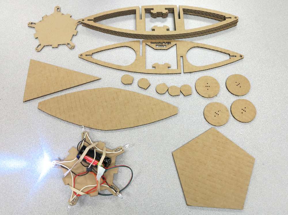
Parol Lantern Lighting Experiments
Here are some example of Parol Lanterns using LED lighting which are inexpensive and efficient (LED tutorial). Order Parol Kits!
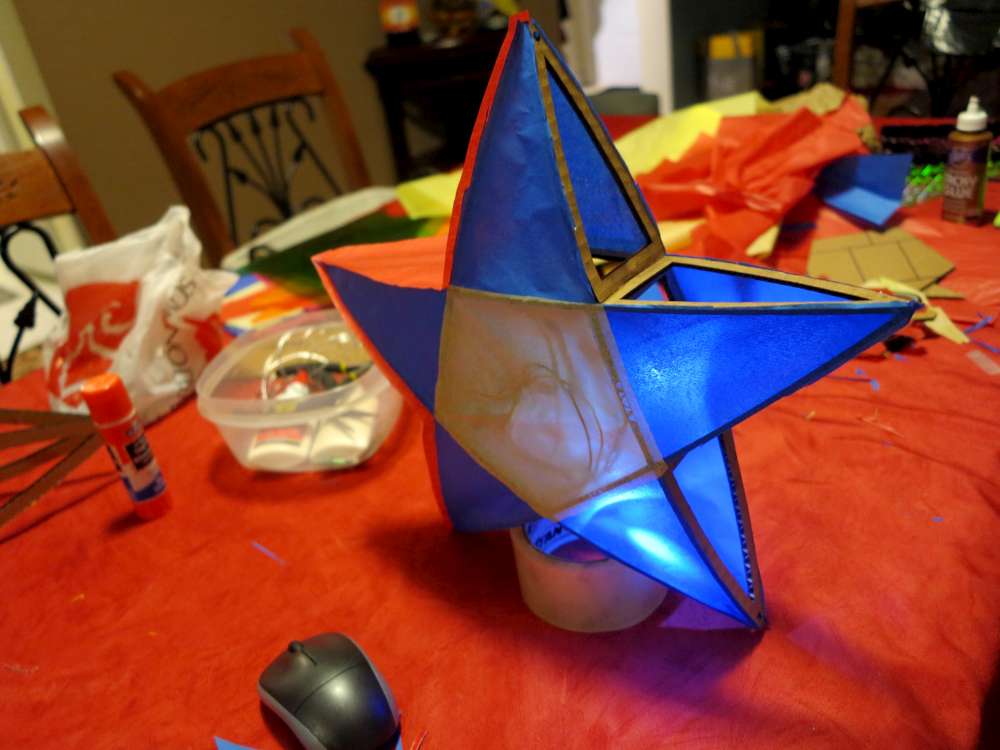
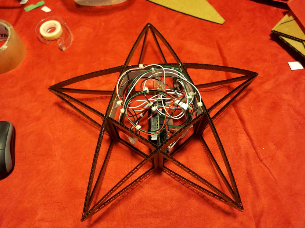
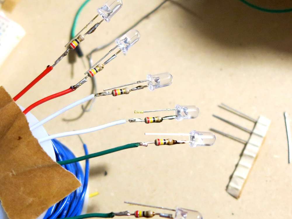
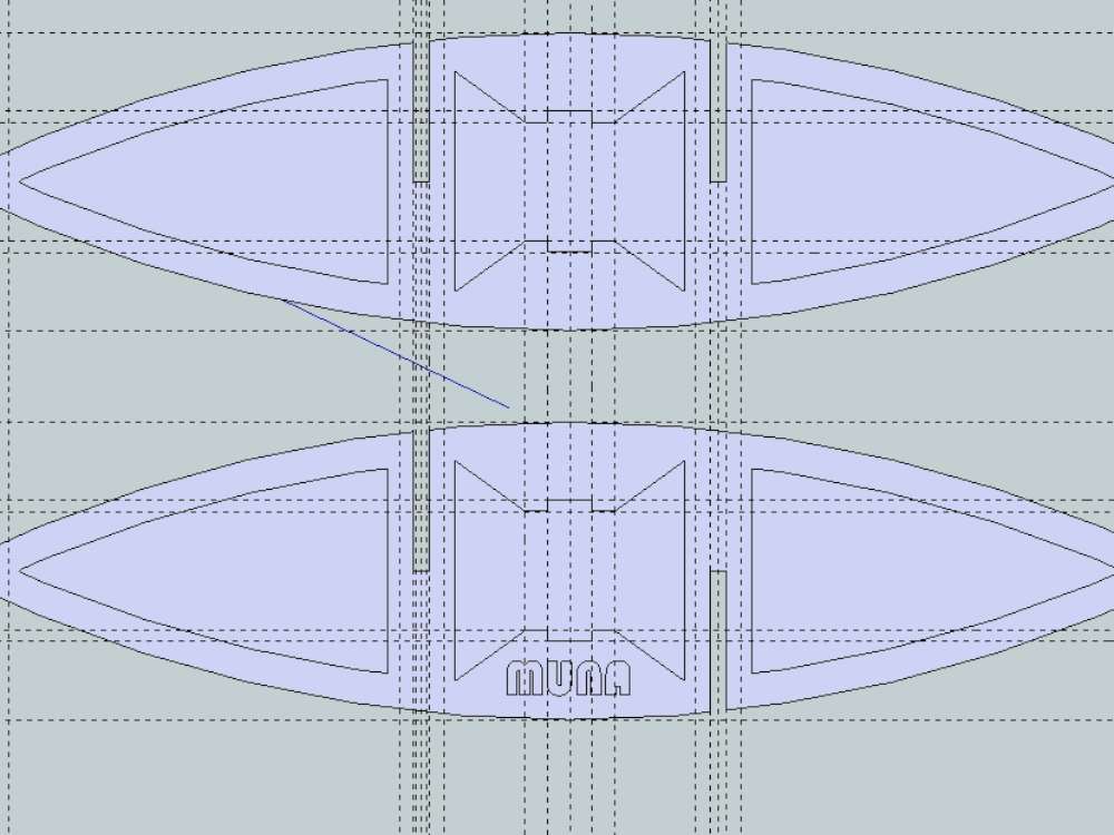
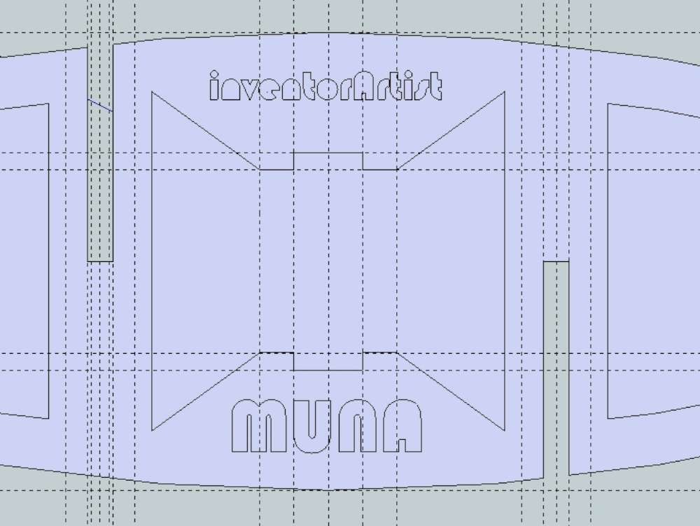
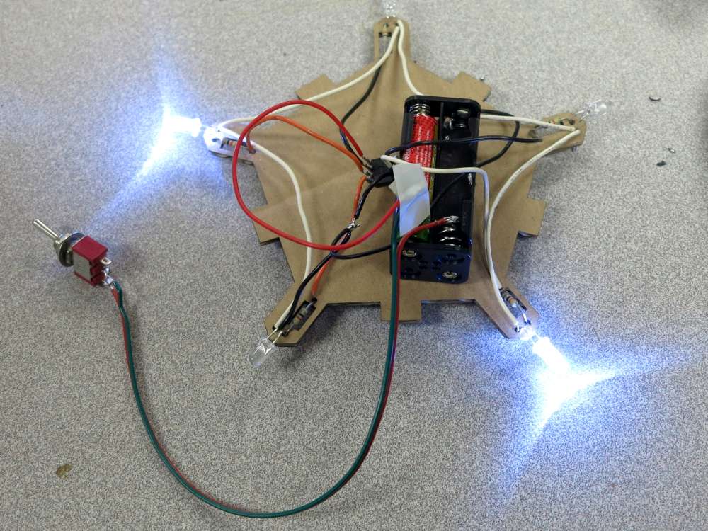
Six LED Arduino Parol Lights
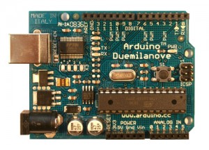
I used an Arduino and an infra red receiver (TSOP4838) so the light sequences can be controlled with any TV remote.
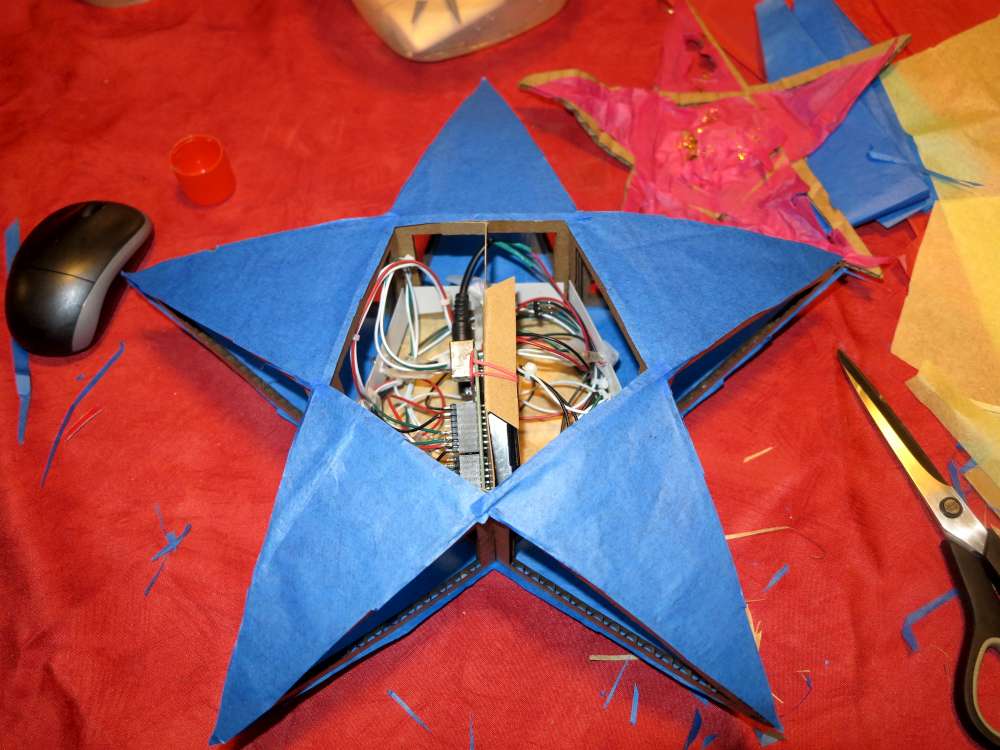
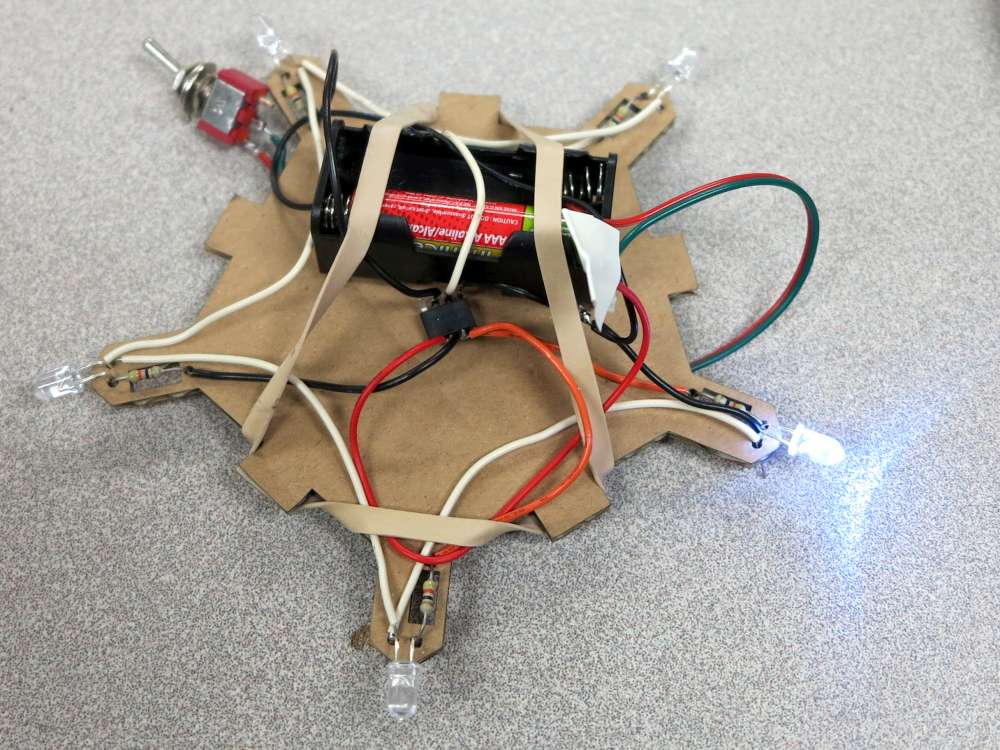
I wired each LED to a header so the Arduino can easily be removed for programming. I also wired a battery pack to a jack for easy removal. The LEDs are wired to pins 3, 5, 6, 9, 10, and 11 since they have PWM (Pulse Width Modulation) and can control the brightness of the LEDs. I used 25 ohm resistors (since they were lying around). I’m not sure if that’s a good value but it seems to work and nothing gets warm. I think pin 3 and 11 PWM is disabled because of the IR receiver.
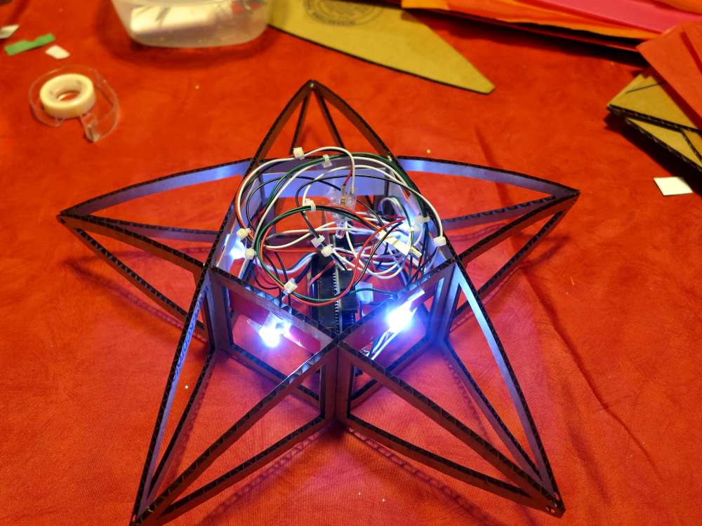
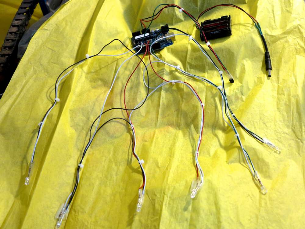
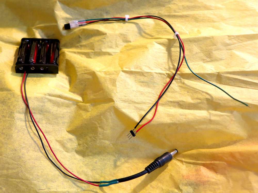
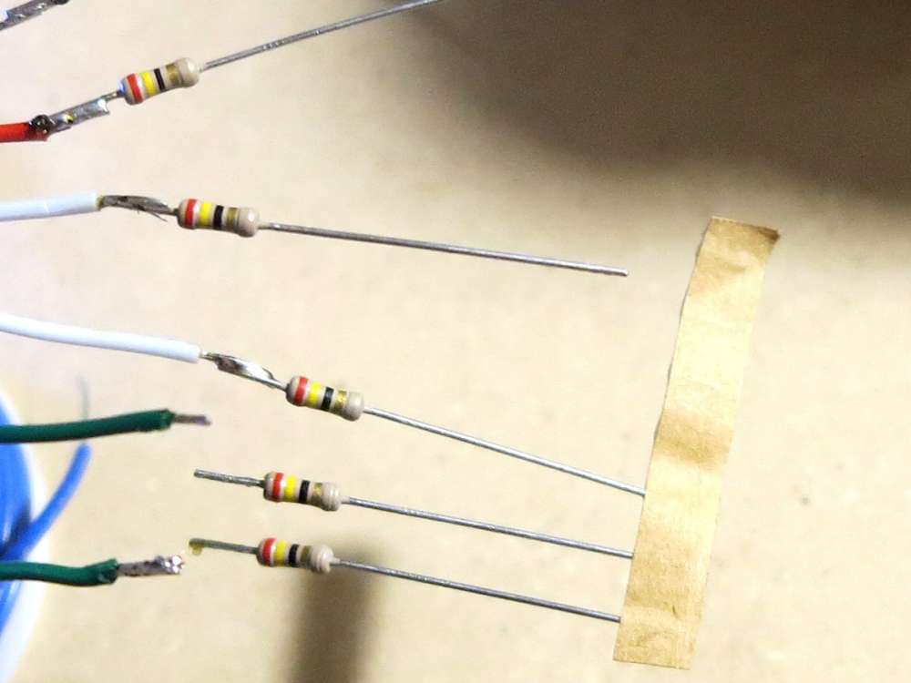
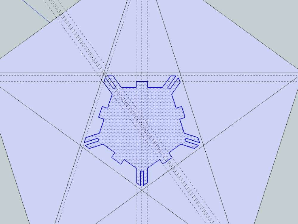
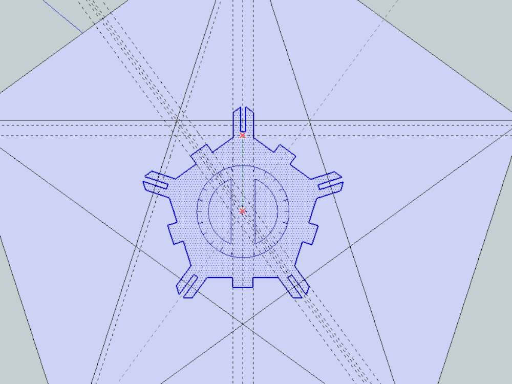
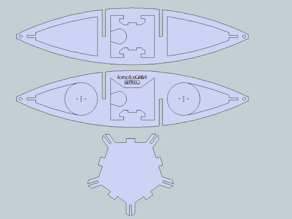
Below you can see the wiring. In retrospect I don’t need such a long wire harness. Also I think I will make a removable spoked plate that has all the electronics attached. Then the wiring can be fastened to a structure as they are soldered. I’ll need to add some features to the template as well as create a couple new parts for this.

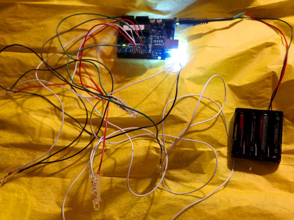
Here is the code for the above video. I temporarily took the remote control out since I burned out my IR-RX (infra red receiver).
/*
Parol Lantern
Darcy Whyte, http://inventorArtist.com, darcy@inventorArtist.com

          3(p9)

   1(p5)  2(p6)  4(p10)

       0(p3)  5(p11)

*/

//visualization
int led[] = {3,5,6,9,10,11}; //pins 5-10 can fade, 3,11 in use by IR
int ledN = 5;

int brightness = 255;

//speed
int frameDelay = 200;
int frameN = 4;
int frame = 0;
long lastFrame = 0;

void setup() {
  Serial.begin(9600);
  for (int i = 0; i<=5;i++) {
    pinMode(led[i], OUTPUT);
  }

}

void loop() {
  //soft
  Serial.println("soft");
  for (int j = 0;j<=3;j++){
  for (int i = 0; i<=255;i++) {
    analogWrite(led[2], i);
    delay(7);
  }
  for (int i = 0; i<=255;i++) {
    analogWrite(led[2], 255-i);
    analogWrite(led[3], i);
    delay(7);
  }
  for (int i = 0; i<=255;i++) {
    analogWrite(led[3], 255-i);
    analogWrite(led[1], i);
    analogWrite(led[4], i);
    delay(7);
  }
  for (int i = 0; i<=255;i++) {
    analogWrite(led[1], 255-i);
    analogWrite(led[4], 255-i);
    analogWrite(led[0], i);
    analogWrite(led[5], i);
    delay(7);
  }
  for (int i = 0; i<=255;i++) {
    analogWrite(led[0], 255-i);
    analogWrite(led[5], 255-i);
    delay(7);
  }
  delay(4000);
  }

  //rotate
  Serial.println("rotate");
  for (int j = 200;j>=20;j=j-15){
  for (int i = 0; i<=1;i++) {
    analogWrite(led[0], 255);
    delay(j);
    analogWrite(led[0], 0);
    analogWrite(led[1], 255);
    delay(j);
    analogWrite(led[1], 0);
    analogWrite(led[3], 255);
    delay(j);
    analogWrite(led[3], 0);
    analogWrite(led[4], 255);
    delay(j);
    analogWrite(led[4], 0);
    analogWrite(led[5], 255);
    delay(j);
    analogWrite(led[5], 0);
       // delay(300);
  }
  }

  //supernova
  Serial.println("supernova");
  for (int i = 0; i<=300;i++) {
    analogWrite(led[random(6)], random(200));
    delay(10);
    //deviceKey = random(2047);
  }
  for (int i = 0; i<=5;i++) {analogWrite(led[i], 0);}

    delay(4000);

  //flicker
  Serial.println("flicker");
  for (int i = 0; i<=10;i++) {
    for (int i = 0; i<=5;i++) {analogWrite(led[i], 255);}
    delay(50);
    for (int i = 0; i<=5;i++) {analogWrite(led[i], 0);}
    delay(50);
  }
  for (int i = 0; i<=5;i++) {analogWrite(led[i], 0);}

  delay(5000);

}
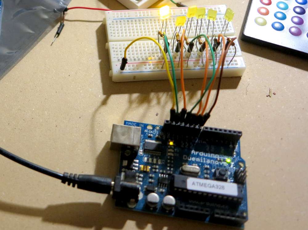
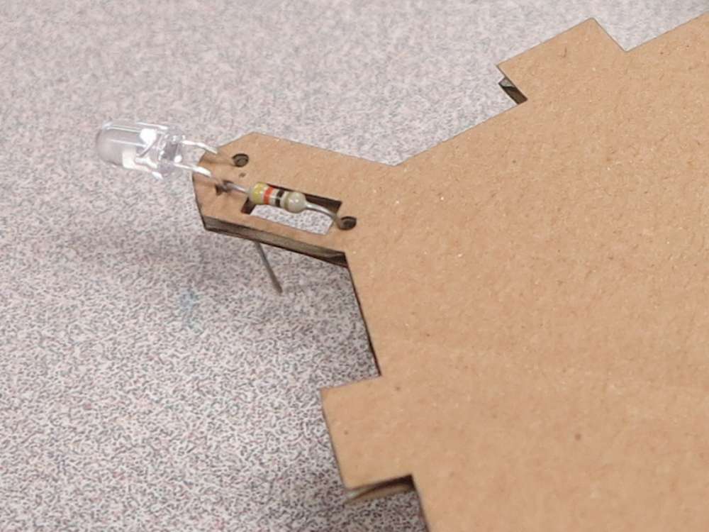
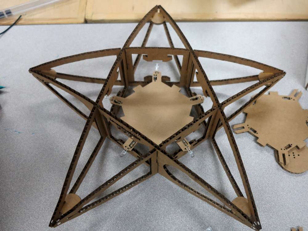
Five LED Tiny
Here’s a very inexpensive method of getting five LEDs going! You can get these Tiny ATTINY85-20PU chips for lass than a dollar. Here is a tutorial on how to program them using the Arduino IDE and a breadboard. The breadboard can be replaced by this programmer.
The Tiny only has two PWM pins on it. That’s fine by me but apparently you can play around with it to get the same effect.
Here are a few pictures of one in action. Notice I figured out a better way to wire it using a cardboard plate. The plate holds everything in place for easy soldering and the tray is removable.
Here’s the Tiny code so far:
/*
  Blink
  Turns on an LED on for one second, then off for one second, repeatedly.

  This example code is in the public domain.
 */

int led[] = {0,1,2,3,4};
int ledN = 5;

// the setup routine runs once when you press reset:
void setup() {
  // initialize the digital pin as an output.
  for(int i = 0; i<ledN; i++)
  {
    pinMode(led[i], OUTPUT);
  }
}

void analogToPWM(int pin, int speed, String type){
  if(type == "in"){
      for(int fadeValue = 0; fadeValue <= 255; fadeValue++) {
        delayMicroseconds(10+fadeValue); // Approximately 10% duty cycle @ 1KHz
        digitalWrite(led[pin], LOW);
        delayMicroseconds(speed);
        digitalWrite(led[pin], HIGH);
      }
      digitalWrite(led[pin], LOW);
  }
  else{
    for(int fadeValue = 255; fadeValue >= 0; fadeValue--) {
      digitalWrite(pin, HIGH);
      delayMicroseconds(10+fadeValue); // Approximately 10% duty cycle @ 1KHz
      digitalWrite(led[pin], LOW);
      delayMicroseconds(speed);
    }
    digitalWrite(led[pin], LOW);
  }
}

// the loop routine runs over and over again forever:
void loop() {
  for(int i = 0; i<ledN; i++){
    if(i == 2 || i == 3 || i == 4){
      analogToPWM(led[i], 150, "in");
      analogToPWM(led[i], 150, "out");
    }
    else{
      for (int j = 0; j<=255; j++) {
        analogWrite(led[i], j);
        delayMicroseconds(200);
      }
      analogWrite(led[i], 0);
      for (int j = 255; j>0; j--) {
        analogWrite(led[i], j);
        delayMicroseconds(200);
      }
    }
  }
}
LED Strips
There are these cool LED Pixels and LED Strips. They contain shift registers and PWM hardware so you can control all the LEDs on the strip individually using just three lines. I’ve not tried this yet as I didn’t have any of the parts on hand (I only started the project at the end of November) but here are some links and tutorials:
LED Shelf Project
Arduino PWM Shift Library (Arduino Forum, Forum2)
Example using Shift Registers
Possible Supplier, Link2, Link3
Example in Arduino Forum
Shift Registers and PWM Chips
These are a great way to control lots of LEDs with a microcontroller such as Arduino.
TLC5940 (PWM)
TLC5951 (which was used on the Firefly project)
SN74HC595N Shift register
Simple Throwie Lighting
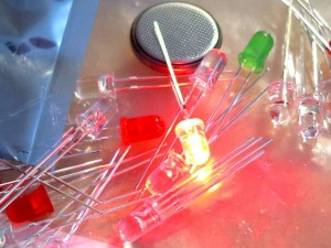
LED lights!
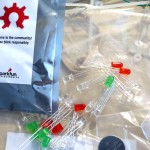
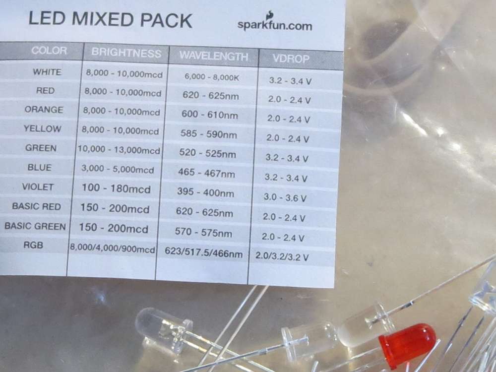 If that’s a little tricky for your taste here’s a simpler method. While looking for a part I came across a bag of goodies that was part of a swag bag from Sparkfun from World Makerfaire NYC. It turns out to be a kit to make throwies.
Feel free to have a look at this tutorial on how to make throwies.
I think that’s something to try especially since the people I’m doing this don’t know anything about electronics. So why not start with the simplest electronic project.
Throwies are easy. You take a “coin cell” and then put an LED against it. Presto! Instant light. You can tape them together and then attach them to your projects.
Thanks Sparkfun!
NoMi Lava Light
Another one I have floating around is this cool lava lamp. Michael the designer actually gave me one a while back to try out. I assembled it and it actually inspired me to go a little deeper into electronics and get a proper soldering iron and be more open to the assembly of electronics.
If you want one of these I’m pretty sure he is selling them at his site. They’re easy to make and give off lots of colorful light!
Here’s something on hackaday: http://hackaday.com/2014/01/07/controlling-cheap-awesome-christmas-lights/
http://www.ofbrooklyn.com/2014/01/15/adventures-in-wearable-electronics-light-up-dress/
Got one of these boards to try out:
http://fritzing.org/projects/tlc5940-breakout-with-atmega328
Here is a link to the schematics for the circuit board I gave you.
Here is the BOM:
1 atmega328 package dip; version Atmega328-20PU; type ATMEGA328; variant dip28 THT
2 Packages: package dil28-3; chip TLC5940; variant -nt
2 Electrolytic Capacitor package 100 mil [THT, electrolytic]; capacitance 10μF; voltage 6.3V
3 Capacitor package cap-pth-small2; variant pth2
36 10k Ω Resistor package THT; tolerance ±5%; bands 4; resistance 10kΩ; pin spacing 400 mil
5 220 Ω Resistor package THT; tolerance ±5%; bands 4; resistance 220Ω; pin spacing 400 mil
(Optional) 1 Power Jack package power_jack_pth_lock; type 5.5mm barrel; variant pth_lock
(Optional) 2 Red LED – 3mm package 3 mm [THT]; leg yes; color Red (633nm)
(Optional – Atmega Reset button) 1 Pushbutton package [THT]
(Optional) 1 Toggle Switch package THT; switching circuit SPDT
(Optional) 1 Voltage Regulator – 5V package TO220 [THT]; voltage 5V
2 Ceramic Disk Capacitor package THT; rated voltage 200V; capacitance 22pF; capacitor type Ceramic AND 1 Crystal package THT; frequency 16 Mhz; type crystal; pin spacing 5.08mm
OR
1 Resonator package resonator-pth; frequency 10/16MHz; variant pth
http://www.hobbytronics.co.uk/arduino-attiny
Another link..
Link
You mean Gervais on Industrial? I just looked it up. I’m supposing they’re closed by now. But that’s another supplier I’ll know about for next time, thanks!
Why didn’t you check Gervais? I guarantee they have a bunch in stock. Gervais is way cooler than Active
Okay found an IR-RX (IR Receiver). I have a few on order as well.
Active doesn’t have any and nobody has come forward with an IR sensor. I’m going to start looking at what I can take apart. 🙂
Burned out the IR receiver this morning. Just ordered some, pinged friends and am about to do a quick check to see if I have more of them. I may have one more…