Software Tool Chains
 Since I’ve been making things I’ve started to rely more and more on more modern fabrication/prototyping methods. They include:
- CAD (Computer Aided Design)
- CAM (Computer Aided Manufacturing)
- CNC Machines, CNC Laser, 3D Printing
This sounds like a lot of stuff and a lot of learning but be assured it is worth it! And it’s not so bad actually. You recover the time you put into it (and more). And the fun factor is extreme.
I’ve gone from cutting and measuring with hand tools to much more modern techniques in a fairly short amount of time.
Design Tools
Google Sketchup
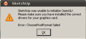
Sketchup was unable to initialize OpenGL! Please make sure you installed the correct drivers for your graphics card. Error: ChoosePixelFormat failed
Sketchup is a great free program for designing objects and systems. They have a pro version as well. The big limitation of the free version is the ability to get different formats in and out of it. But it still works out with the methods outlined below.
You can download a Windows or Mac version. It’s easy to install.
I was able to run this on a Linux Ubuntu using WINE as follows.
Sketchup Linux Installation
- Moved the file to /home/darcy/.wine/drive_c (I’m not sure if this was necessary)
- Right click file. Change the properties so that it’s executable.
- Right click file. Open with Wine.
After it installed, I ran the program by going to Wine in the menu/Wine programs. I got the error “Sketchup was unable to initialize OpenGL! Please make sure you installed the correct drivers for your graphics card. Error: ChoosePixelFormat failed”. I needed the following registry change:
- Open wine menu, open C drive (/home/user/.Wine)
- Open Windows Folder
- Find Regedit.exe and run it with Wine
- Navigate to: HKEY_CURRENT_USER\Software\Google\SketchUp6\GLConf ig\Display
- There are three entries – Look at the bottom one, name ‘HW_OK”
- Double click it and change the data from a 0 to a 1
- Run Sketchup
- http://wiki.winehq.org/GoogleSketchup
Sketchup Tips
Sketchup is not like any graphics programs you may be familiar with. It is worth finding some tutorials in youtube and working through them. So don’t waste your time trying to wing it. Youtube tutorials are free and if you watch a couple per night you’ll be up and running in no time.
When you design things you want to think about the fabrication method you hope to use ahead of time. It’s very convenient to think of making your objects from sheets of raw material. You then cut the parts out and fasten them together. When working with sheets this is called the 2D or 2.5D method.
Sketchup Plugins
Bezier Curves: su_bezier_110.rbz
Convert to DXF/STL: skp_to_dxf.rbz
Import DXF: DXF import plugin
2D CNC Rotary Cutting: Sketch-U-CAM plug-in can make g-code for simple work. You can download the plug-in at http://www.phlatforum.com. You can install it by unzipping it into the Sketchup folder found in the “Program Files” folder. It seems to work in Linux under WINE as well.
2D CNC Laser Cutting: I’ve been using a Sketchup plugin called “Flight of Ideas” which exports sketches to SVG files which can then be opened in InkScape or Corel Draw. Many lasers have a “print driver” to send data to them so you can print out of these packages to your cutter. InkScape has a bad print system so for that one your path is to export to a PDF, then use a PDF viewer on the laser. Corel seems to make nice DXF files which my laser works well with.
3D CNC Cutting: I’ve been using MeshCAM (tip from Michal Zalewski) from (http://www.grzsoftware.com) which I am quite happy with. It probably work for 2D Cutting too. You need to export the Sketchup file to an STL file using a plug-in such as STL Exporter. This has been working out very well.
3D Printing: I have been using Repetier and slicing software. It’s really nice software.
Open source STL Exporter Sketchup plugin (once added to the plugin directory, it shows up in the Sketchup tools menu. From there he uses Skeinforge STL to g-code converter. This should work for additive as well as subtractive work.
Apparently this plugin is good for sketchup: http://extensions.
FreeMill: Michal Zalewski mentioned FreeMill from MecSoft as a CAM solution. This looks very nice. After installing it, I noticed that it can import files of type (.vmp .sla/.stl .3dm .wrl .raw .vmp .sla/.stl .3dm .wrl .raw). So theoretically this is a good solution for 3d cutting. So it can work with Sketchup using the STL Exporter. I have tried it. It seems to work. You need to open it as administrator for it to work (right click, open as admin). I was able to get through making one part. There are a few problems to work out.
G-code viewing: There is a Sketchup plugin for viewing the g-code (GPlot1.2). Simple place these files in the plugin directory. It will appear in the plugin menu and will show the last g-code you generated.
I’ve also been using NCPlot to preview any g-code files.
Graphics Rendering
This is the creation of graphics from your design files. This is for promotion or for helping to visualize as part of the design process. http://www.kerkythea.net
Making Gears
Matthias Wendel’s Gear Generator program is a great way to make gears.
Online: gears
More CAD-CAM Tools
CAMBAM
Guy of OttawaRoboics and ArtEngine showed me this. It seems great for simple objects and generates g-code. It seems to work great. The catch is that it’s a Windows only program. The evaluation will eventually expire but the software is reasonably priced. I’ve used it a bit. It’s a little slow going on the data entry and is not really friendly. I can’t imagine how I could do as well with this as Sketchup. But I’m open.
InkScape
This software is free, runs on linux or Windows and works great. It’s an Adobe Illustrator replacement (which is a vector graphics editor). Turns out I’m already using this for my model airplane project. This has been very good for preparing laser files (or further processing files I’ve done in Sketchup). I am still working on getting a path from InkScape directly to the CNC Rotary Cutter.
Solidworks
Micheal Grant of OttawaRobotics and ModLab has been talking this up and has acquired some evaluation licenses for our community. I think this is what the professionals use. The difficulty I have is once your free trial expires the software is quite expensive. I’m not really comfortable with adding a $10,000.00 part to my tool chain when there are good free offerings around. Also, I’m really working in 2D anyway.
Heeks
CAD/CNC: http://www.heeks.net/ (http://code.google.com/p/heekscnc/) (http://code.google.com/p/heekscad/) This was suggested of Andrew Plum of ModLab/ArtEngine. I checked my ubuntu repositories and there’s nothing there. I went to the heeks site and found a link to Ubuntu packages but the link doesn’t work. I sent a note to Dan Heeks asking about it. Dan got back to me quickly and mention they’re not up too much on Linux yet. We’ll see what happens on this one. He said that you need to compile it in linux on your own. I’ll look at that if nothing else works well.
Blender
This is very popular. I’ve not needed to try it yet but it’s on my todo list.
Eagle
This is for circuit board design. I’m in the process of learning this.
Other CAD
Rhino 3d: http://www.rhino3d.com/ was suggested to my by Michal Zalewski who wrote this amazing article: http://lcamtuf.coredump.cx/guerrilla_cnc1.shtml Alibre CAD: Also recommended by Michal Zalewski. He said it’s less expensive than Rhino.
CNC Machines
These are the machines that actually do the fabrication. Laser and CNC Rotary are very useful. 3D Printing is still a little weak despite what you read. The good machines are still very expensive. You can access them through mail order services such as Ponoko, Shapeways and other services.
Also your local machine shop will likely have these machines.
You can also get access to them via your local hackspace.
I believe that public libraries will eventually start to have some of these machines. Also places that have photocopiers and such may get on board.
Here are some machines I use:
CNC Lasers
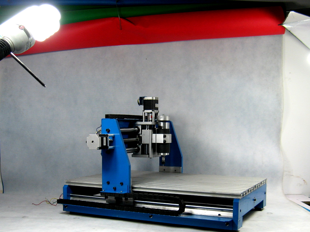
This is my Chinese laser cutter. Works great.
Epilogue Laser Machines: Vector Cutting With Inkscape
 This machine is great for vector, raster and stamp making. For vector cutting you can prepare your files with Inkscape. As a rule the Epilogue machines use a print driver so you can submit jobs from any software that can print. Except Inkscape since it has a flawed print rendering system. So there is always a step to export it to a PDF and then printing from the PDF to avoid this.
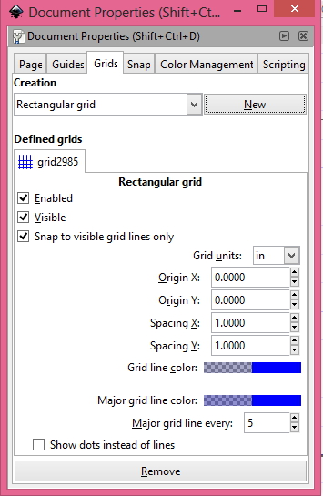
Use a grid in order to help make your drawing accurate. The grid tab is found under the File/DocumentProperties menu. If the grid page is empty click the New button. Change your unit to inches or cm or whatever unit you like and then put the grid size in. You get to have a different setting for X and Y. You may find that you use different settings for making different features. For example you may use 1/4″ to make some features then change the grid to 1/8″ to make other features. Switching back and forth so there are only as many grid lines as you need.
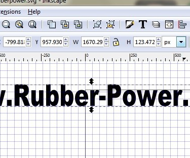 You can re-size objects to make them exact as follows. Once the object is drawn, you can select it and change its size to a specific size. First change the dropdown at the far right (in the image) to your unit of choice. Then select the lock to keep the aspect ratio. Punch in the length or width and hit enter. Now unlock and make any fine adjustments. For example in the image I set the width of my object to 4″ and the heigh came out to just a bit under 1″. So I unlocked and changed it to exactly 4×1″ so I could remember it better.
 Once you have all your cuts made change the line size to 0.001″. Highlight everything, then click the paint brush looking button that is labeled as “Edit objects colors…”. Make sure the fill is set to nothing, the stroke paint is set to black with full opacity. On the Stroke Style tab, choose your unit and .001″ and hit enter. Dismiss that dialog.
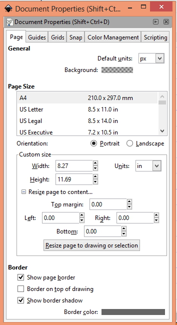 Change the size of your document. In the File/DocumentProperties menu on the first page you can change the unit and document size at the bottom. Make this the same as your drawing. In my example below I made it 5×5″.
If your document is 5×5″ and your page size is 5×5″, you’ll want to center the drawing on the page. Select all your drawing, then go to the centering dialog. Make sure page is selected then click center vertical and horizontal.
Save your file as an Inkscape SVG.
Save your file as a PDF using SaveAsCopy. Be sure to save the dimensions of the file into the file name. Example: Myfile_2p3x6.5.pdf. In this example the file is 2.3×6.5″.
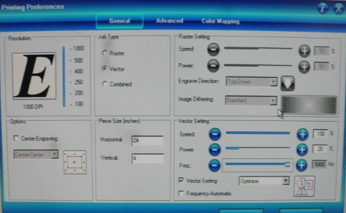
Look in the manual to get feed rates, power recommendations and frequency for cutting your material. Check the internet and ask around too.
Load the PDF onto the laser PC using a memory stick. You can open it right on the stick. Open up the PDF by double clicking it. I noticed our machine has SumatraPDF 1.7. Go to File Print. The advanced tab is all default:
Powering up the laser.
-Start the exhaust system.
-Start the laser.
-Place test material such as cardboard on the cutting area (from top or front).
-Turn on laser pointer.
-Turn off XY axis.
-Press focus.
-Free wheel the gantry out and bring out the focus probe.
-Press up and down till the probe is touching (swing it like a pendulum to see if it is free or touching).
-Put the probe away.
-Free wheel the gantry to the start of your work (top left).
-Press go to enable XY axis.
The Preferences screen is where the action starts.
First we do a cut at 100 percent Speed and very low power (5% or less) to verify the setup. Stop it as soon as you’re sure (stop/reset).
Click Okay, the print to send the job.
Pull the test material and place your real work piece in the machine and focus (press XY, focus, then updown to touch off the probe).
Go to go back online. Now load your real power and speed levels and print to send the job to the laser.
Click OK, then print.
On laser, click job, then Go.
3D Printers
http://www.youtube.com/watch?v=XdZTnlDnX8k
CNC Rotary Cutters
Related
MeshLAB: For converting between formats. http://meshlab.sourceforge.net/
http://www.thebitbangtheory.com/2012/01/cnc-software-toolchain-linux/
http://replicat.org/generators
http://lcamtuf.coredump.cx/gcnc/
http://www.cnc-club.ru/forum/viewtopic.php?f=15&t=35&start=20#p194
http://sourceforge.net/apps/mediawiki/pycam/index.php?title=Installation
http://sourceforge.net/apps/mediawiki/pycam/index.php?title=Hints_for_2D_modeling_with_Inkscape_(SVG)
Other opinions I’ve heard along the way:
“… in general, there are substantial differences between general 3D modeling programs and CAD tools, so I wouldn’t be getting my hopes up when it comes to conveniently using Blender or Sketchup”. —Michal Zalewski
“Solidworks and SolidEdge get my vote. These 2 really are miles beyond anything else in 3d CAD. You can use AutoCAD, etc. fairly effectively for 2d stuff assuming you don’t want to moch up your assemblies (or don’t want to do that easily?).
That said you absolutely need to have someone show you the basics with Solidworks. Learning it on your own is very painful (I learned this way but it took substantially longer to learn then people I’ve taught since then).
Cool things in solidworks (these should all be in solidedge as well):
2d and 3d parametric design and driving dimensions. Believe it or not having designs that scale nicely are not built into the majority of CAD software outside Solidworks, SolidEdge and Inventor (I struggled hard with AutoCAD on this before switching to Solidworks).
assemblies allow you to visualize your finished product better. You can also test clearances using this. On my deltabot I assemble every part to it’s connecting parts before printing so that I can check it’s range of motion, etc… very handy.
Parametric assemblies and blocks allow you to scale features across multiple parts without having to edit each individually.
Really it’s about automation. Things you can spend hours on in other CAD software are done automatically in Solidworks and that’s why I use it, because it allows you to generalize a design and then edit the parameters you actually care about until it’s perfect.” — RobI would second the tag. AutoCad has always been very
aggressively focused on a 2D “electronic drafting table” paradigm,
which is workable in the construction/architectural industry, but
really kind of broken in a lot fundamental ways. There were
prototypes done in the 60s at MIT and other places that remain more
progressive than autoCAD.Solidwork is a neat package, but, as Rob said, kind of heavy-duty to
learn on your own. In my opinion, a nice in-between package is Rhino
— it’s a surface, rather than a solid modeler, and not really
parametric in any strong way, but, as I always describe it: “it’s like
autoCAD, but in 3D and without the suck.”Very gentle learning curve, powerful suite of commands, very intuitive
and user-friendly.I’ve worked with autoCAD everyday for years, and it still feels like a
struggle. Every now and then I open Rhino and can just breathe a sigh
of relief. — Liav
http://www.thingiverse.com/thing:5986
To do the conversion from DAE format to OBJ or STL, download MeshLab – it is also free.
To make corrections to the design, get netfabb Basic – also free.
http://geargenerator.com/
This plugin for inkscape claims to import svg.
http://www.uli-tessel.de/suruby.htm
But it needs other plugins.
Am trying this: http://rubyinstaller.org/downloads/
and: http://sketchucation.com/forums/viewtopic.php?t=36430
http://www.crai.archi.fr/rld/plugin_details.php?id=33
Mach3 zero https://www.youtube.com/watch?v=G4DeVa8rzA0
http://www.cnccookbook.com/MTCNCTipsTechniques.htm
Guy from reddit gave this plugin for sketchup for getting to dxf.
This might work to get from svg to sketchup Create SVG file in Inkscape
Import SVG file into Blender
In Blender, do all your extrudes/bevels, etc.
In Blender, convert any Curve objects to Mesh objects [SketchUp chokes importing Blender curves, but not Blender meshes]
Export your Blender file as a COLLADA .dae file
Import the .dae file into SketchUp
Continue editing in SketchUp and export from SketchUp to Google Earth
bender tutorial http://en.wikibooks.org/wiki/Blender_3D:_Noob_to_Pro
Import SVG http://sketchucation.com/forums/viewtopic.php?f=180&p=99818
another try
http://extensions.sketchup.com/en/content/sketchup-stl
http://makezine.com/2014/03/17/10-essential-accessories-for-your-cnc/
http://beatty-robotics.com/
Making 3d objects to print
Step One
Download Google SketchUp
http://sketchup.google.com/
STL Import
http://sketchuptips.blogspot.com/2010…
STL Export
http://www.guitar-list.com/download-s…
http://capolight.wordpress.com/2010/0…
http://sketchuptips.blogspot.com/2010…
Or
Download MeshLab to convert SketchUp files to .STL format
http://meshlab.sourceforge.net/
Step Two
Download netfabb the free studio version to “fix” STL files
http://www.netfabb.com/
Step Three
Bring .STL file to Skinning program
Thanks to
http://edutechwiki.unige.ch/en/Sketch…
https://www.youtube.com/watch?v=mIOUiSW0FAU
http://wiki.nycresistor.com/wiki/Laser_Power