Facere-Bot
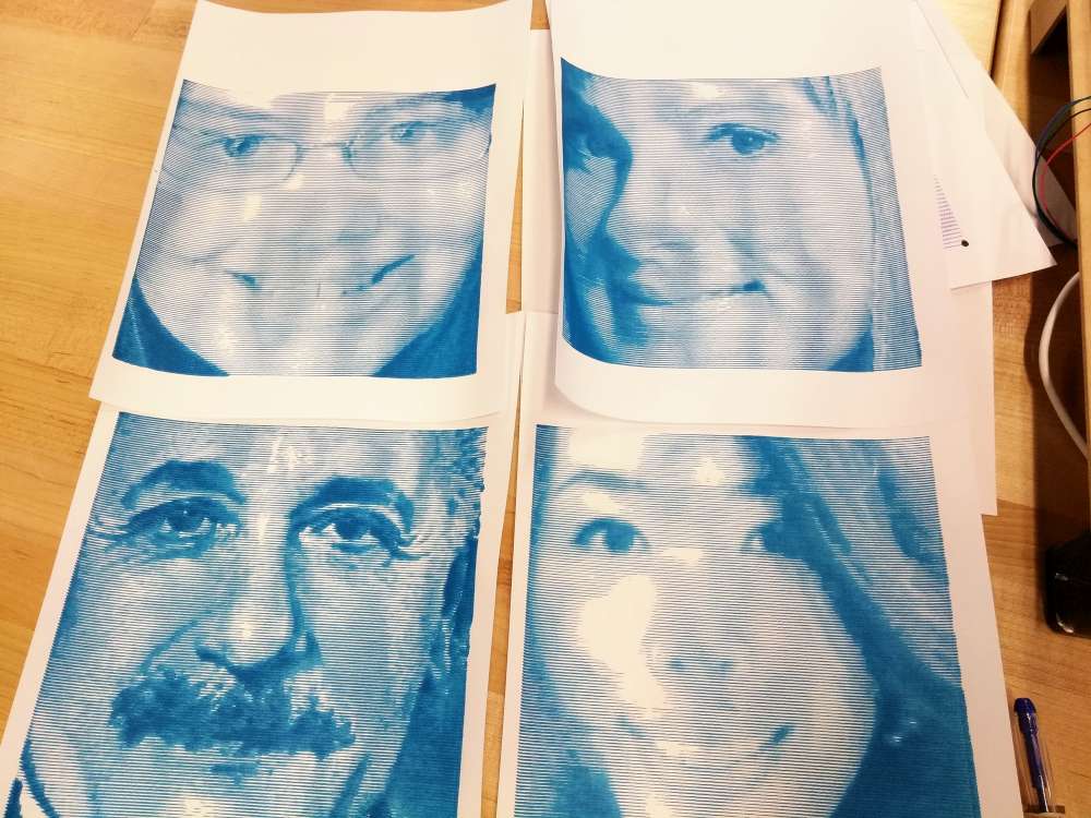
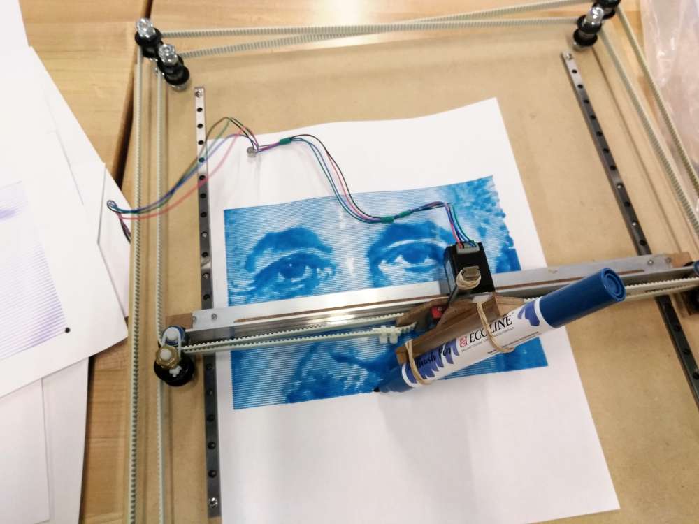
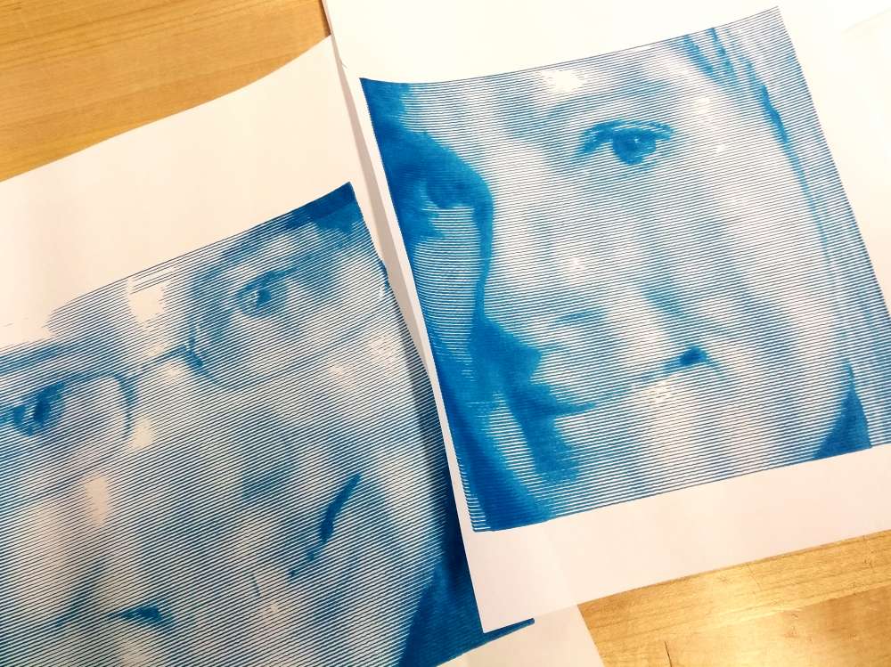
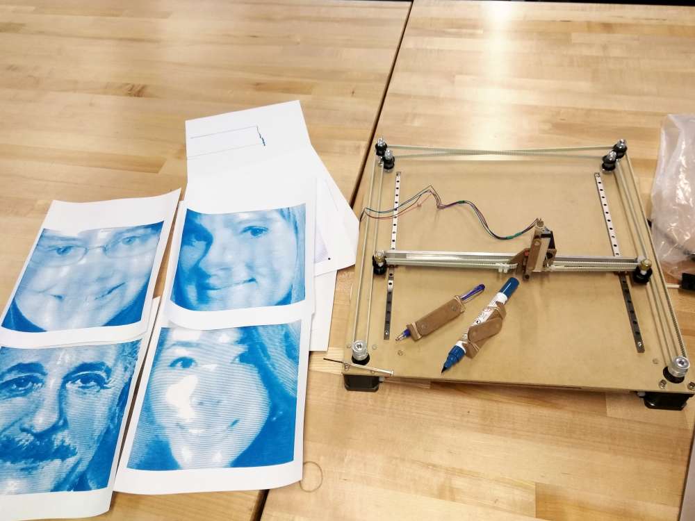
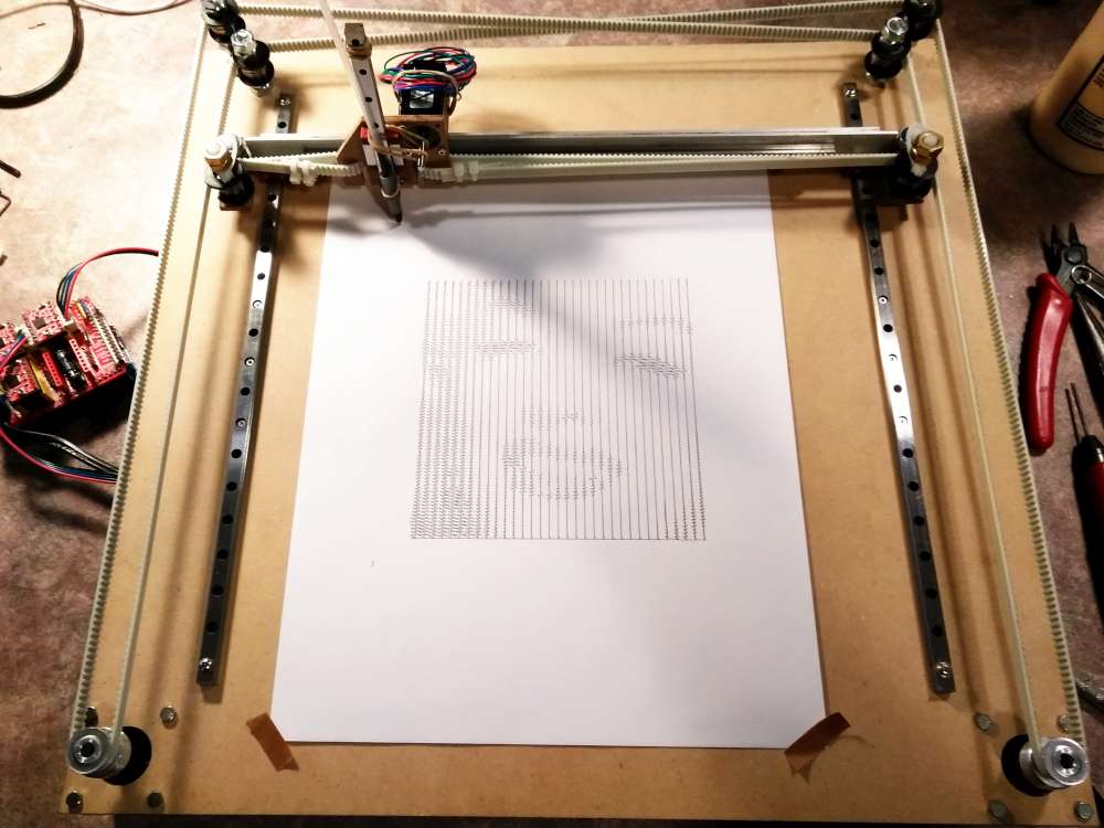
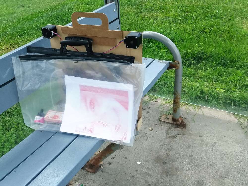
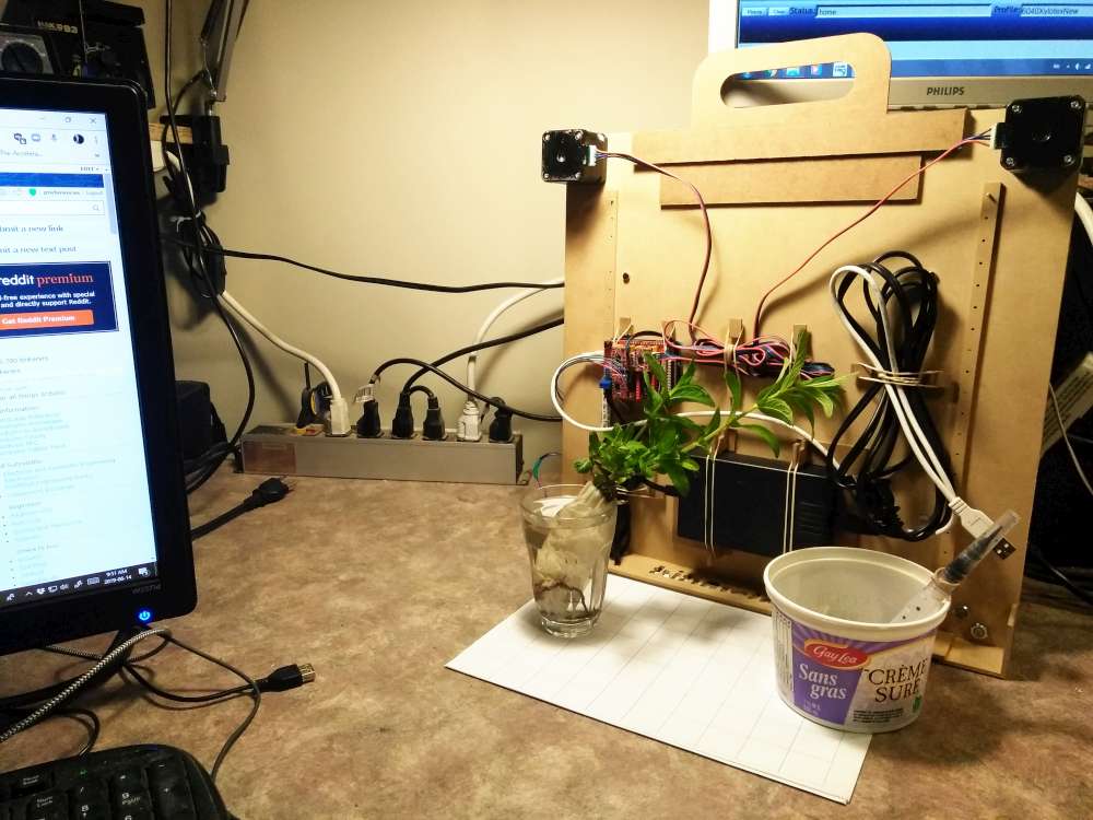
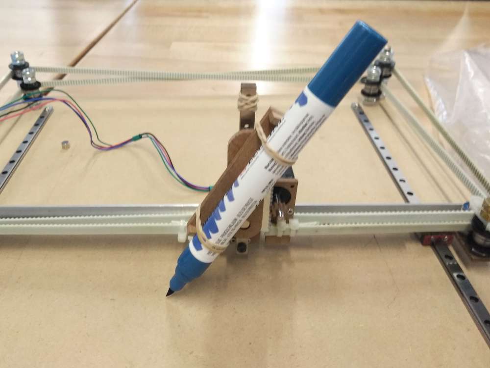
This is an experimental drawing robot. It was designed to be portable, light and fast.
Facere is Latin for “do”, “create” or “make”.
I’ve had a few requests to do a tutorial on how to build this so am adding more details on the machine below. Feel welcome to post questions in the comment section of this post. Also I host a support group for people who want to build stuff like this called hack613. You can join the google group there.
How it’s Made
I wanted something portable (around Letter or A4 size) that was built light so it’s easy to carry and could be fast.
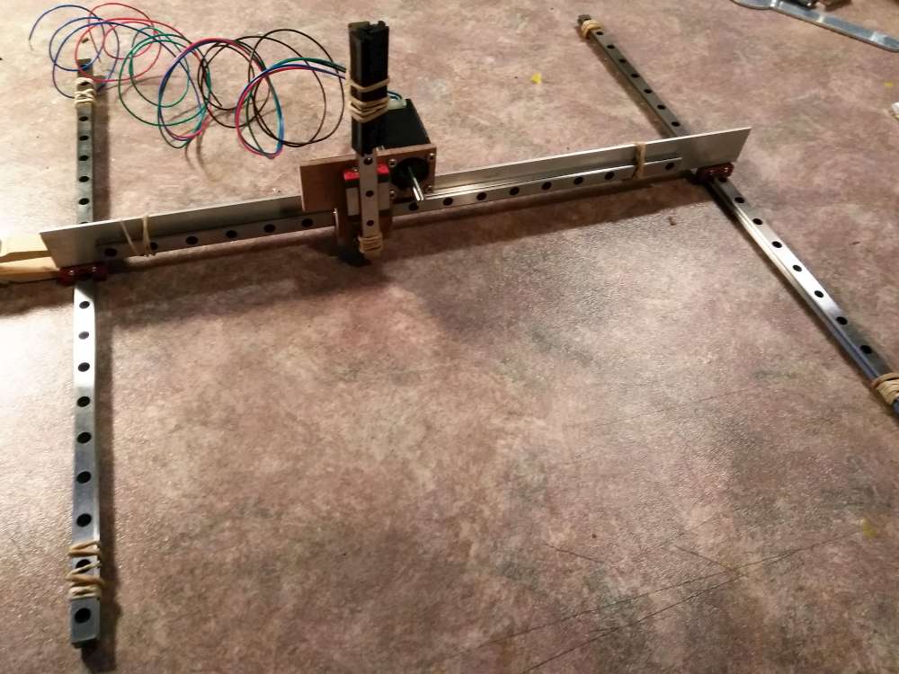
I drew it up roughly in Sketchup Make to do a reality check on what length of linear bearings I’d need. I decided to go with very small linear rail as it seems very rigid and simplifies construction.
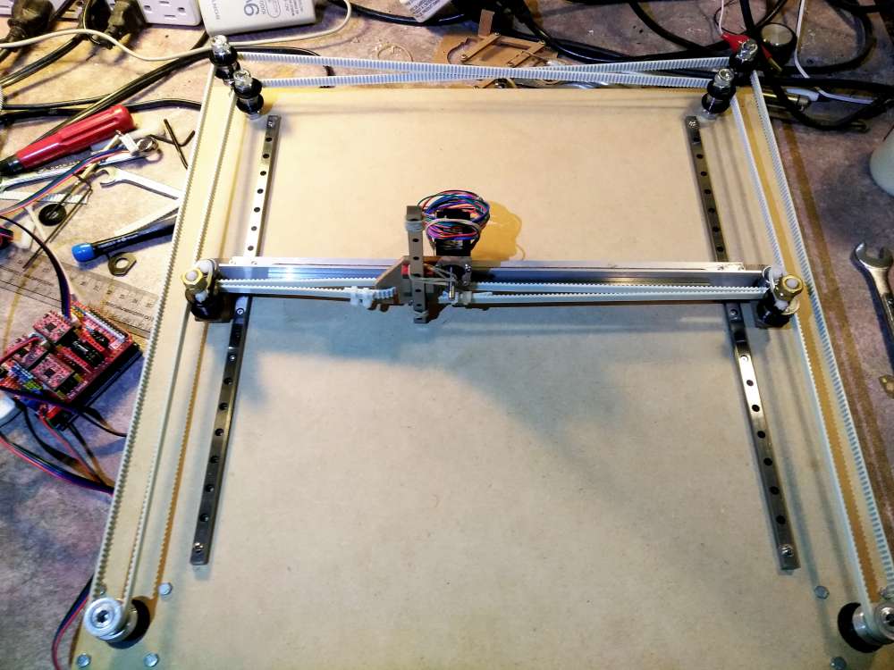
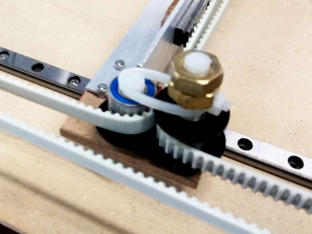
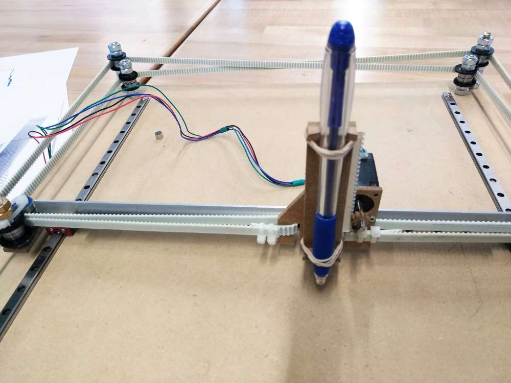
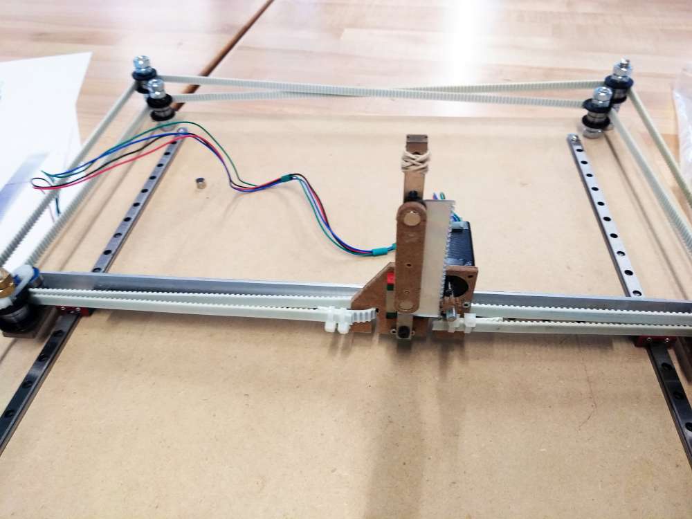
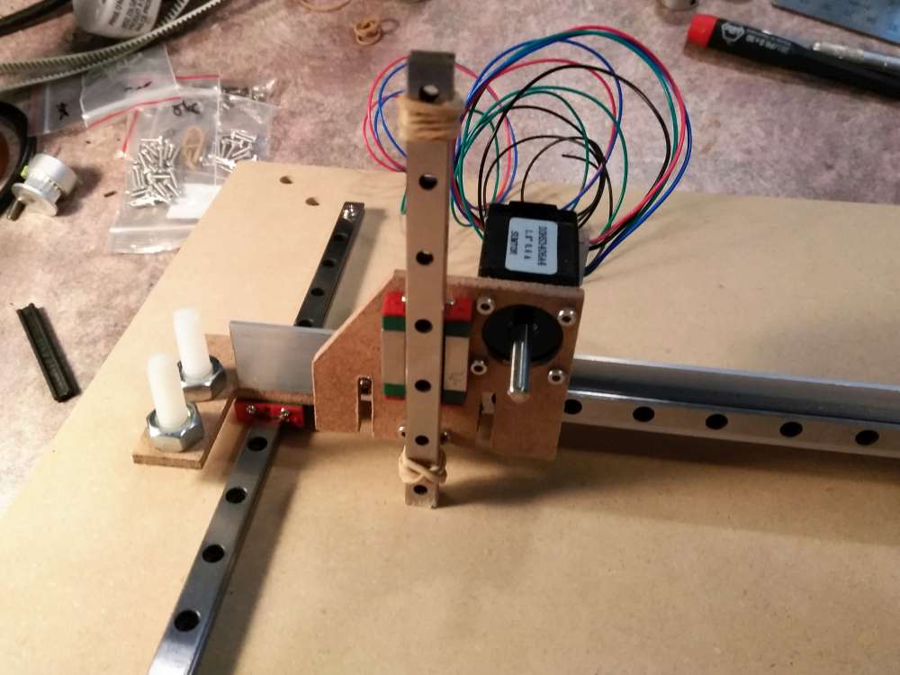
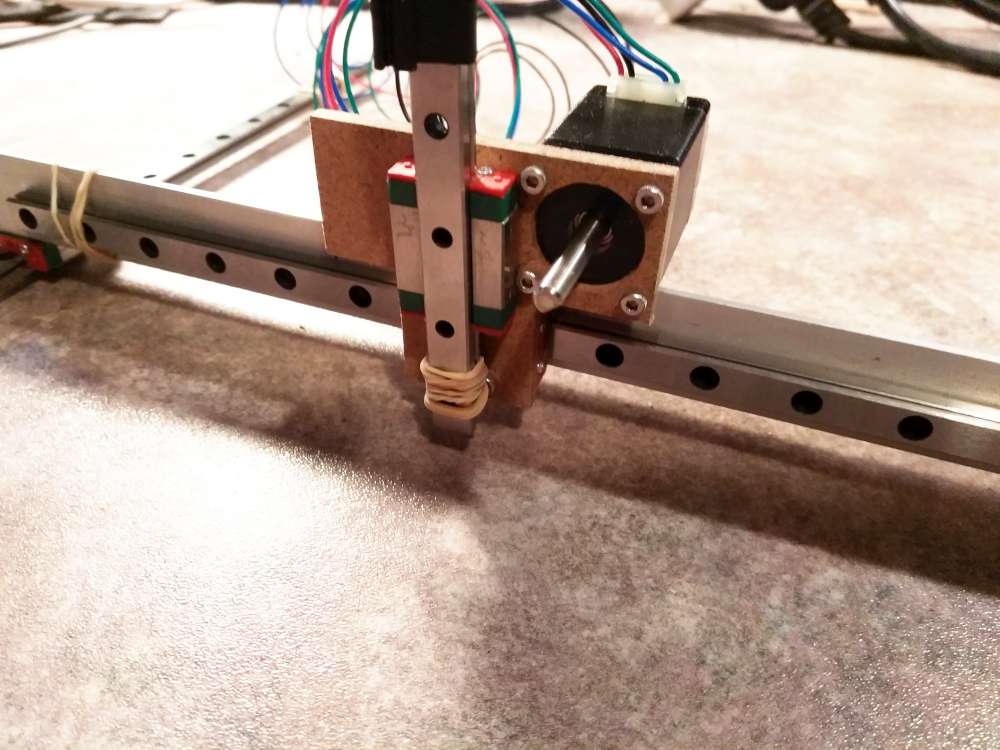
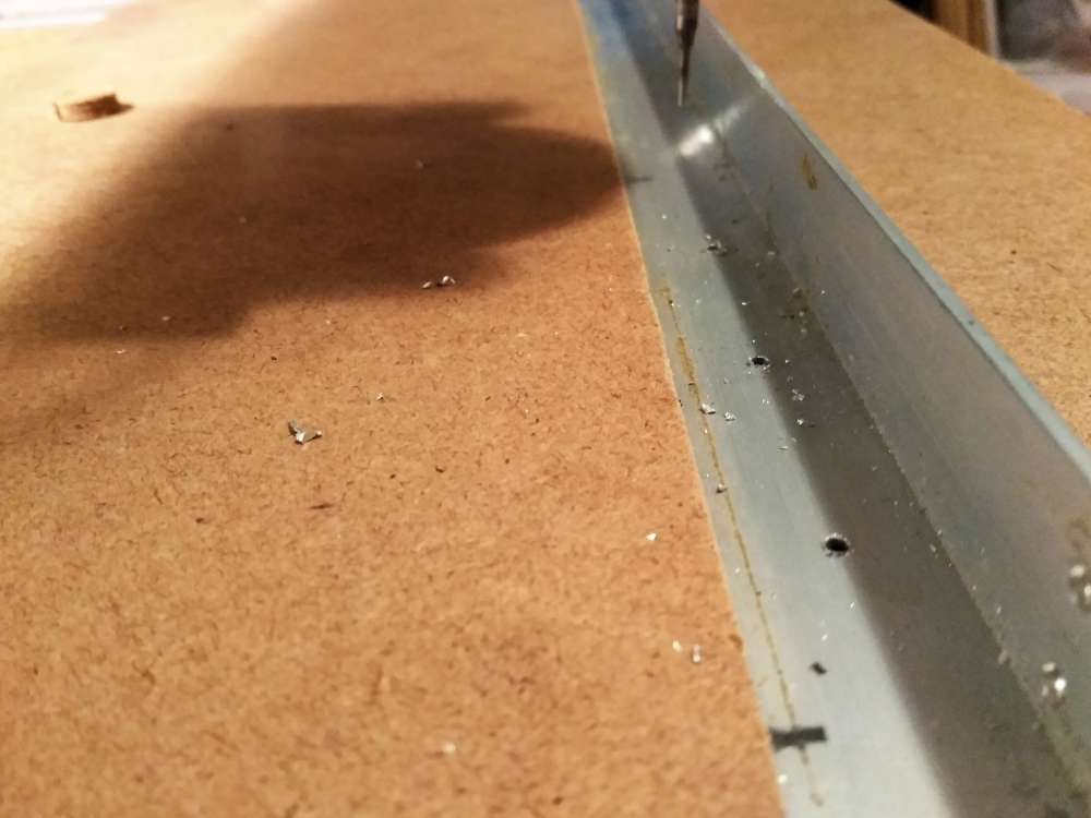
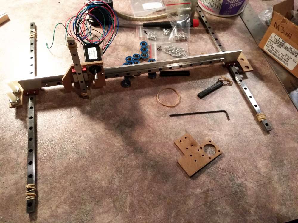
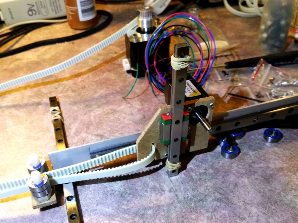
The gantry and carriage are made from a piece of extruded aluminum angle and three plates of hardboard. The plate that forms the carriage has a feature to capture the belts.
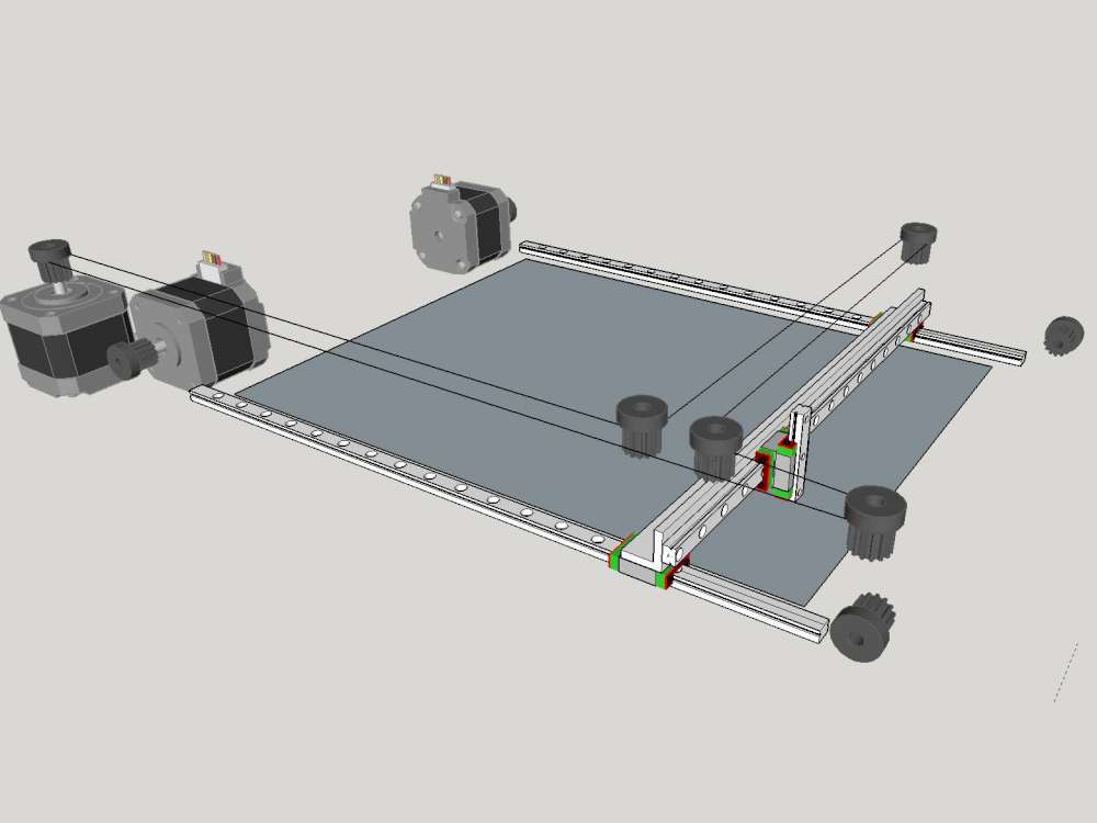
3 motor configuration wasn’t chosen.
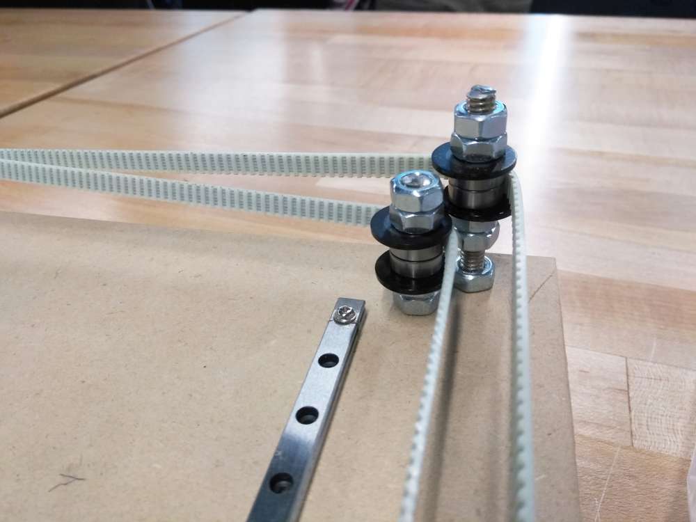
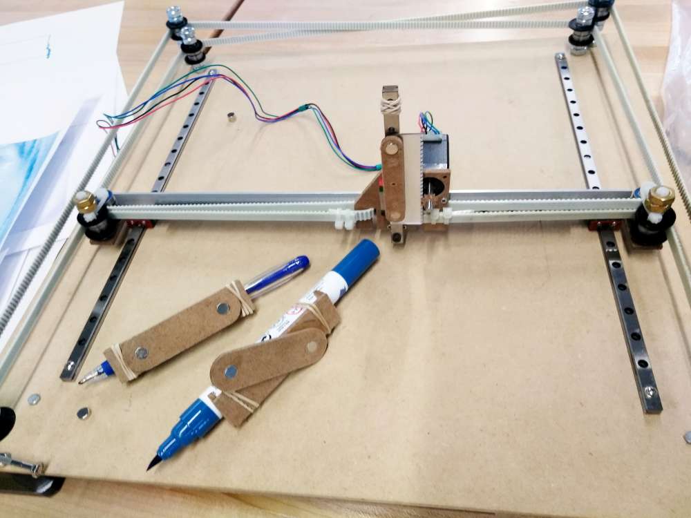
The belt system is coreXY using two Nema17 stepper motors. I considered HBot, Etch A Sketch and a 3 motor configuration of my own. I eliminated HBot since it seems to be more prone to racking of the gantry. The Etch A Sketch seemed to be prone to backlash and racking. I did do some Etch A Sketch experiments and eventually added gears to an actual Etch A Sketch. My own 3 motor configuration looked promising but being new I couldn’t rely on prior art when it came to control and also in a thought experiment it came forward that moving X at the same time as Y would require the X motor to be very fast. Another advantage of coreXY is it is two shorter belts instead one long so you can make a bigger machine with given belt segments.
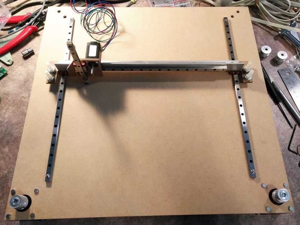
Once I settled on CoreXY I then drew the machine up in Sketchup as a plate. I’d use 1/4-20 bolt/rod, roller skate bearings and delrin washers to constrain the belts. The main bed needed four holes for 4 belt constraints and the gantry needed four holes for the same reason.
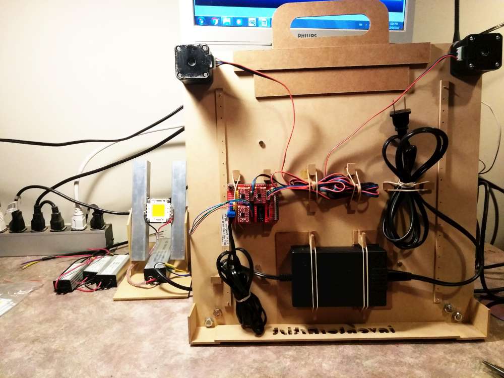
The XY motors became the front “legs” of the machine. I then made risers for the rest of the plate (this leaves enough room under the machine for all the electrical. Also a retractable handle was added. The machine can be carried like a briefcase.
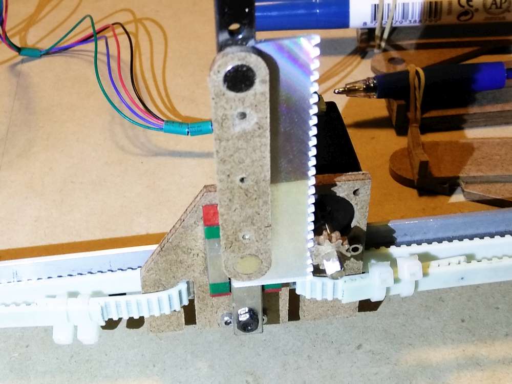
The Z axis was made using a rack and pinion I fashioned from a piece of hardboard for the gear and CD material for the rack. Works pretty well, I’m surprised. I designed the rack and pinion using Matthias Wandel’s gear generator.
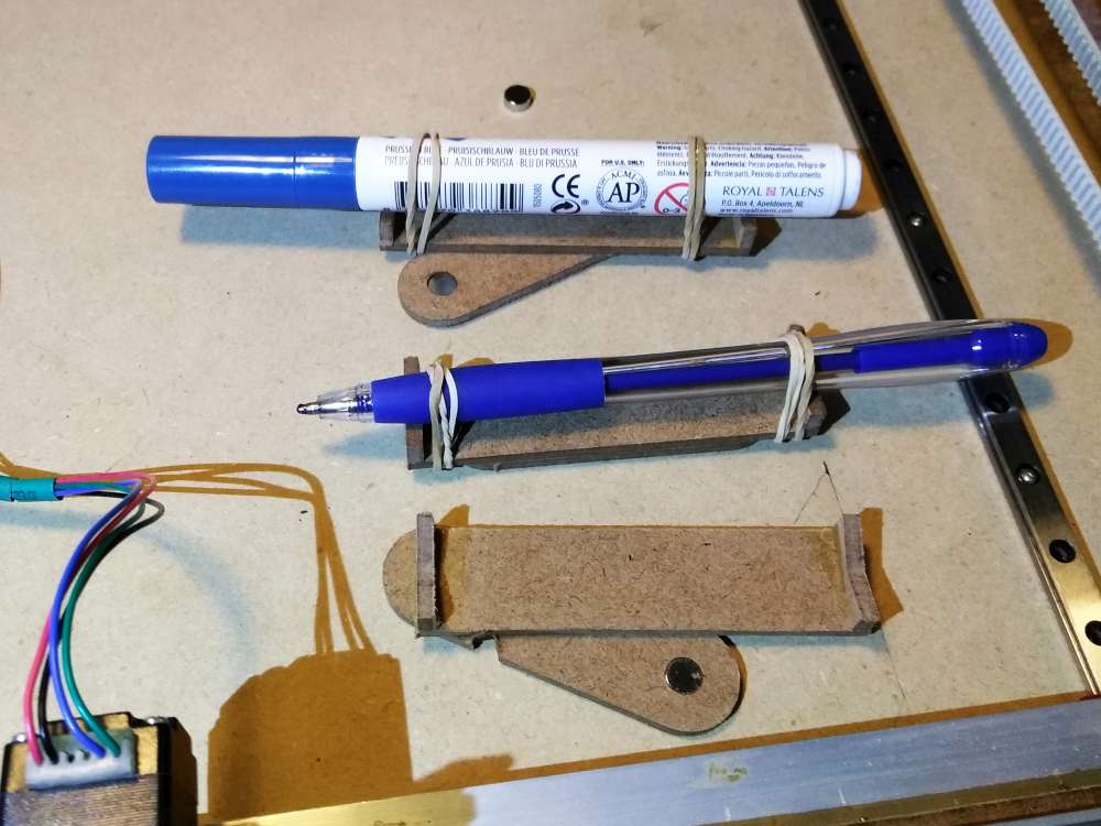
The pen holder is magnetic and it’s very easy to swap and adjust pens.
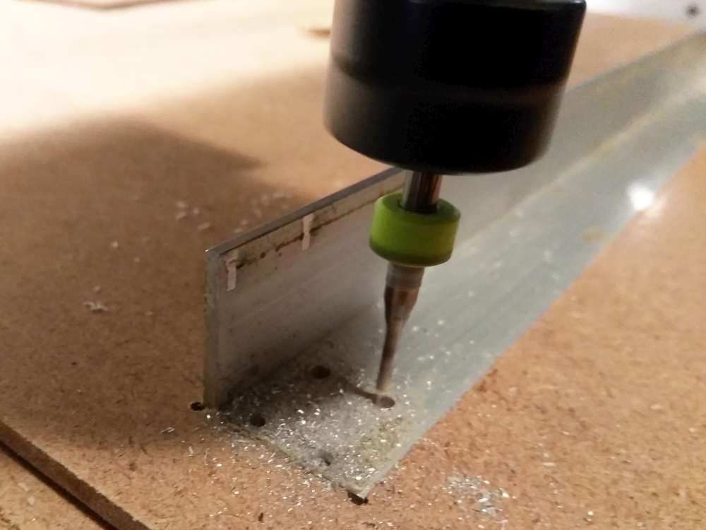
I used a CNC machine to cut out all the parts and glued/bolted it together.
I decided to go with GRBL as firmware for the Arduino so the machine could run g-code. What this means is it is like a CNC machine and you can create g-code from whatever process you want. I just have a pen instead of a cutter.
Bill of Materials
The electrical:
1-Arduino Uno
1-CNC-shield V3
3-A4988 stepper drivers
2-NEMA17 steppers
1-NEMA8 stepper motor
1-12V power supply (6 amps)
Precision parts:
2-MGN7 300mm rail
1-MGN7 250mm rail
1-MGN7 100mm
3-MGN7C bearing blocks
16-Roller skate bearings (1/4″ ID)
2-16 tooth pulley, 5mm ID, 2mm pitch
1-belt, 2mm pitch (will measure soon)
6-bolts for belt control, 1/4-20 sizes to follow
26-1/4-20 nuts (two different thicknesses details to follow)
1-rack and pinion (cut from hardboard and discarded CD)
Fasteners:
8-M3 bolts to mount NEMA17 steppers
4-M2 bolts to mount NEMA8 stepper
20-M2 bolts to mount square rail
Chassis:
hardboard for base, handle, electrical stow
3/4″ extruded aluminum angle
Pen holder:
8-6.3mm x 3mm neodymium magnets
Extra
1-RasberryPi in the works so it can be remotely controlled.
Related
Reddit discussion.
This machine covered in the Arduino Blog and their Instagram.
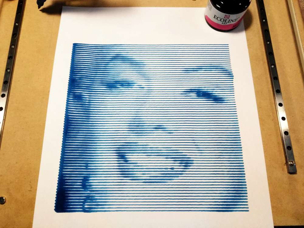
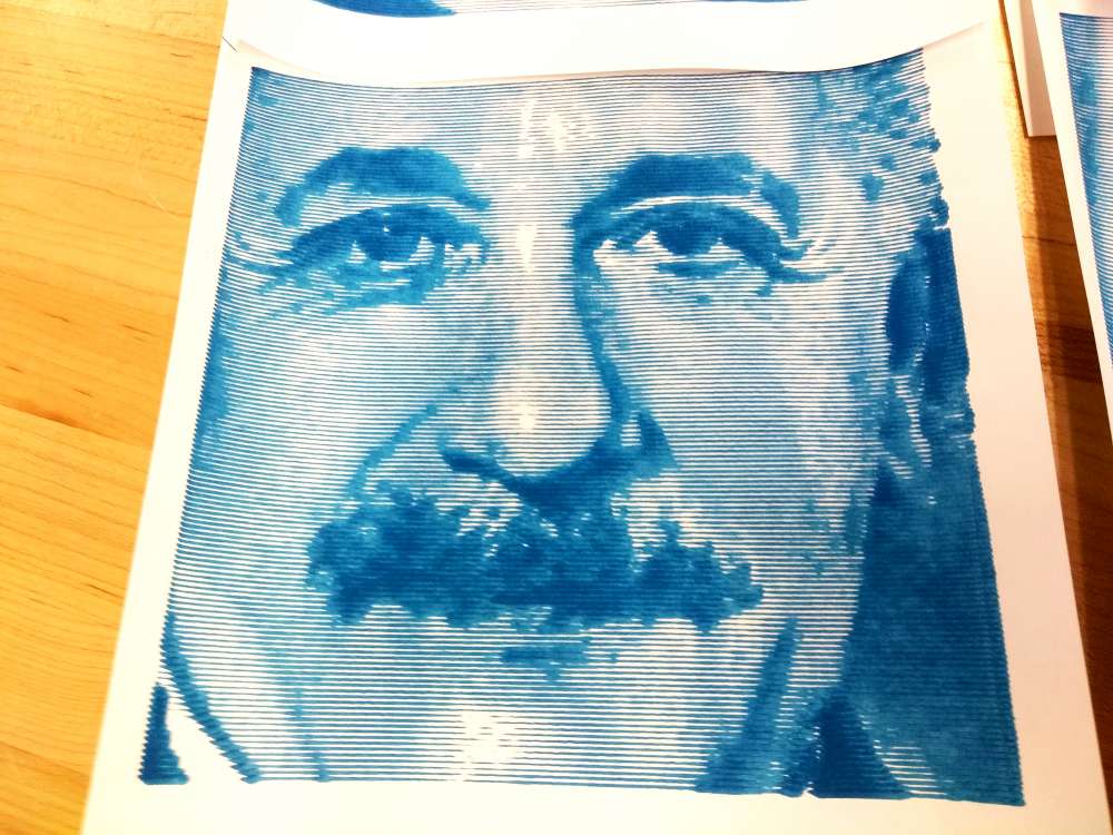
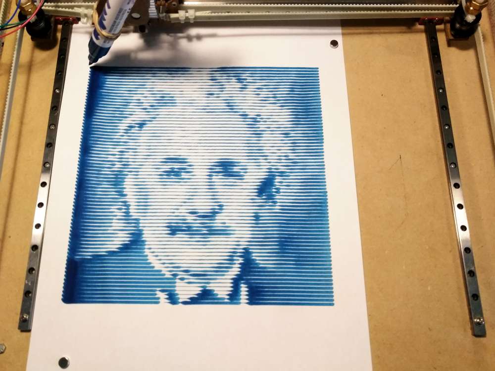
Still waiting for the code and cad files. 🙂 That thing looks amazing.
Please share a code and size of the parts
Watch this space for more information about the bot. I’ll even publish the cad files eventually.
Ok I’m waiting for files