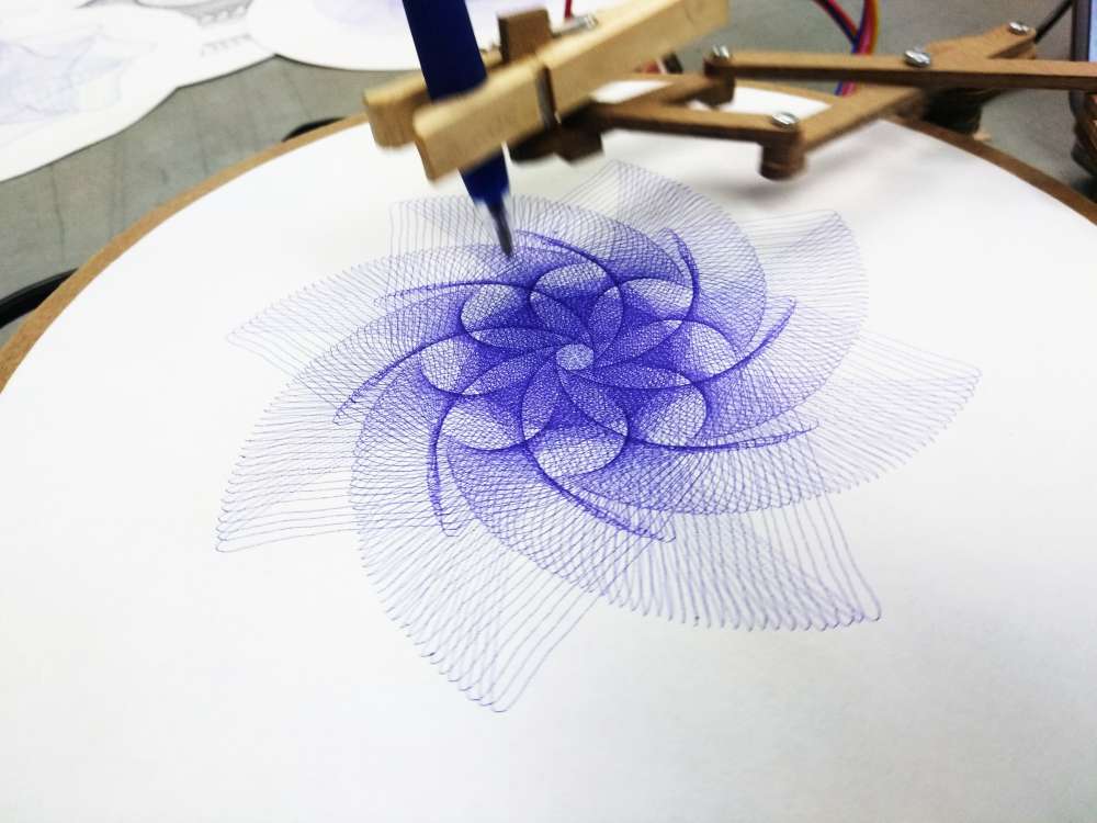
Cycloid-O-Matic
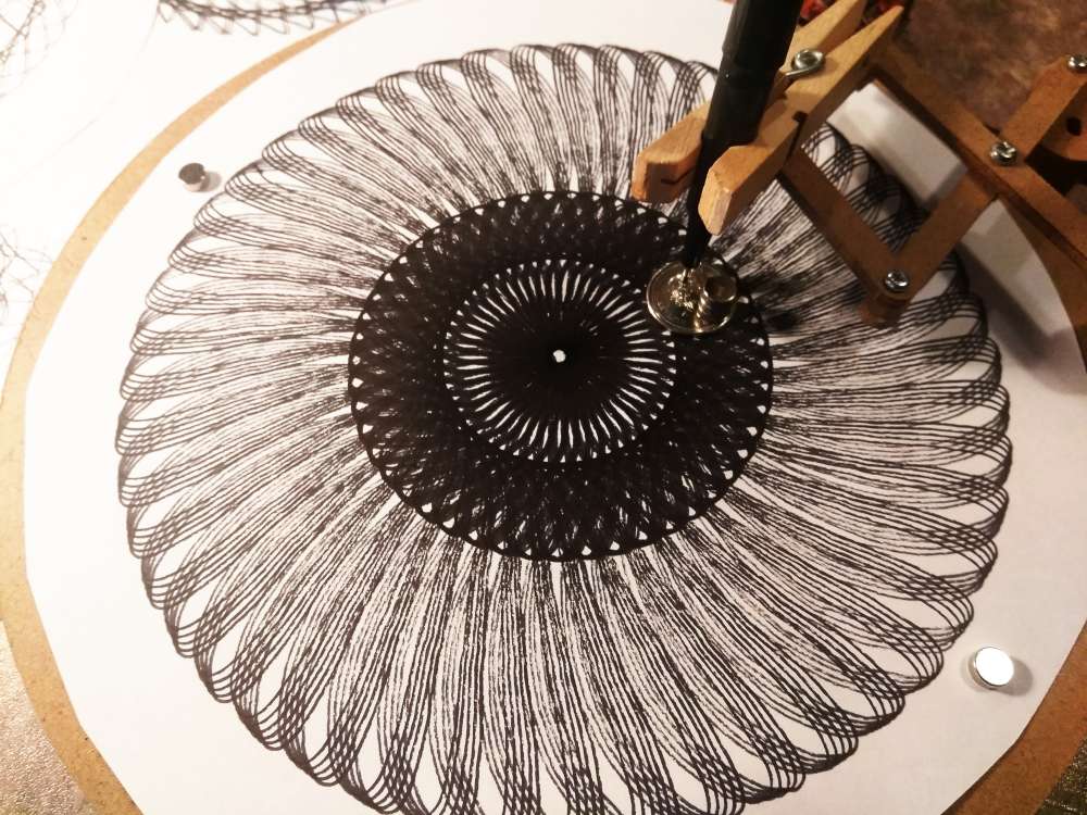
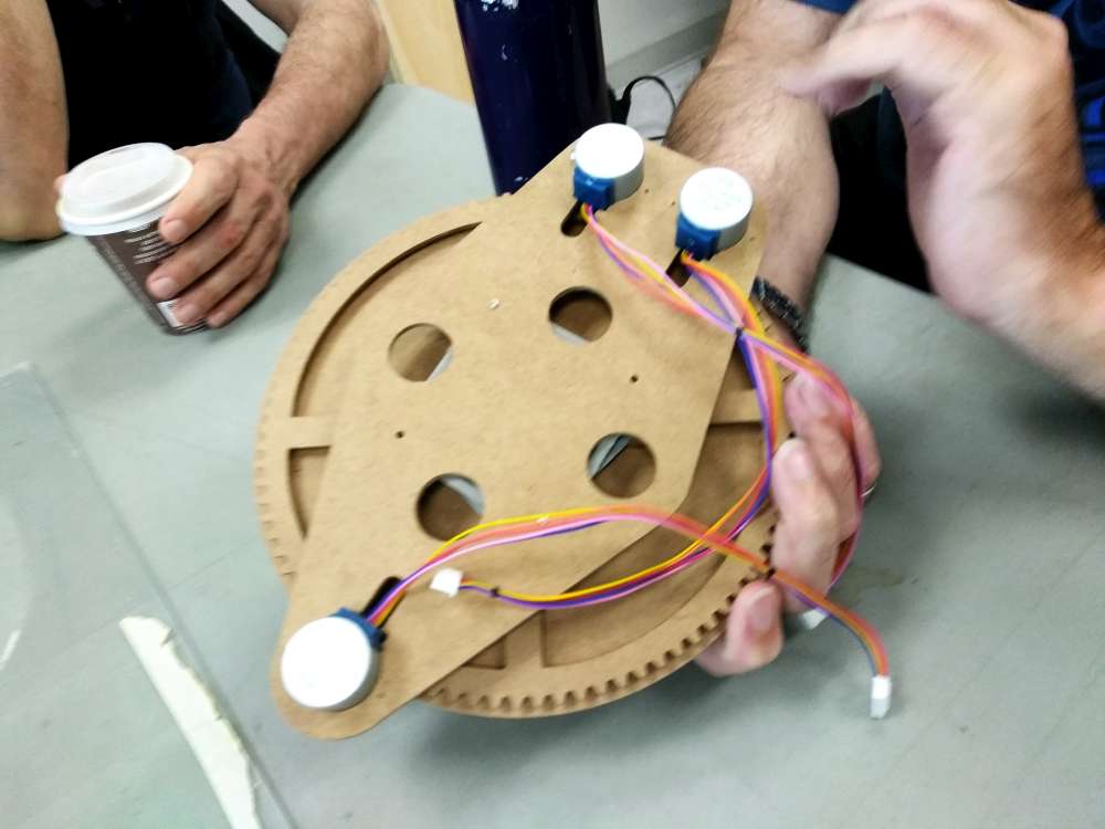
Here’s an installment for the #hack613 challenge (to make a machine out of 28byj-48 steppers). It’s a three-axis cycloid drawing machine.
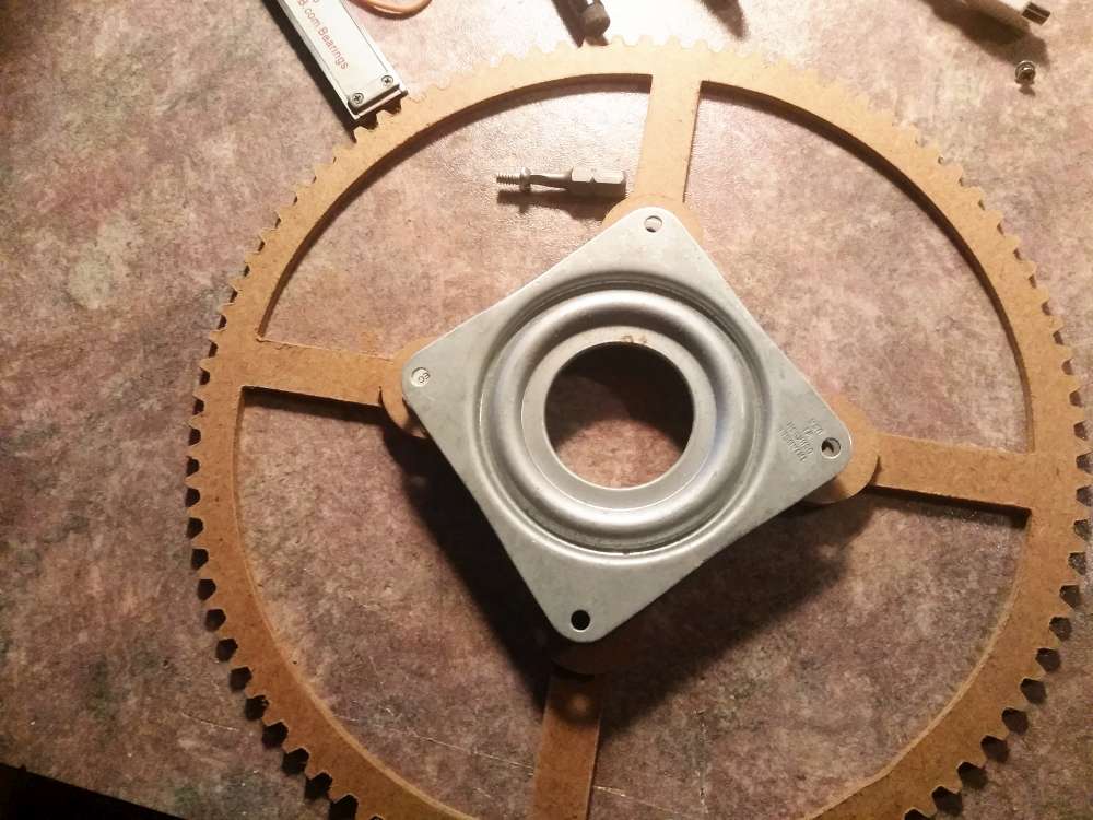
I drew it up in Sketchup and designed the gears using the woodgears.ca gear generator.


28BYJ-48 Motor 10 Second Hack
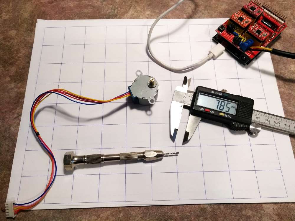
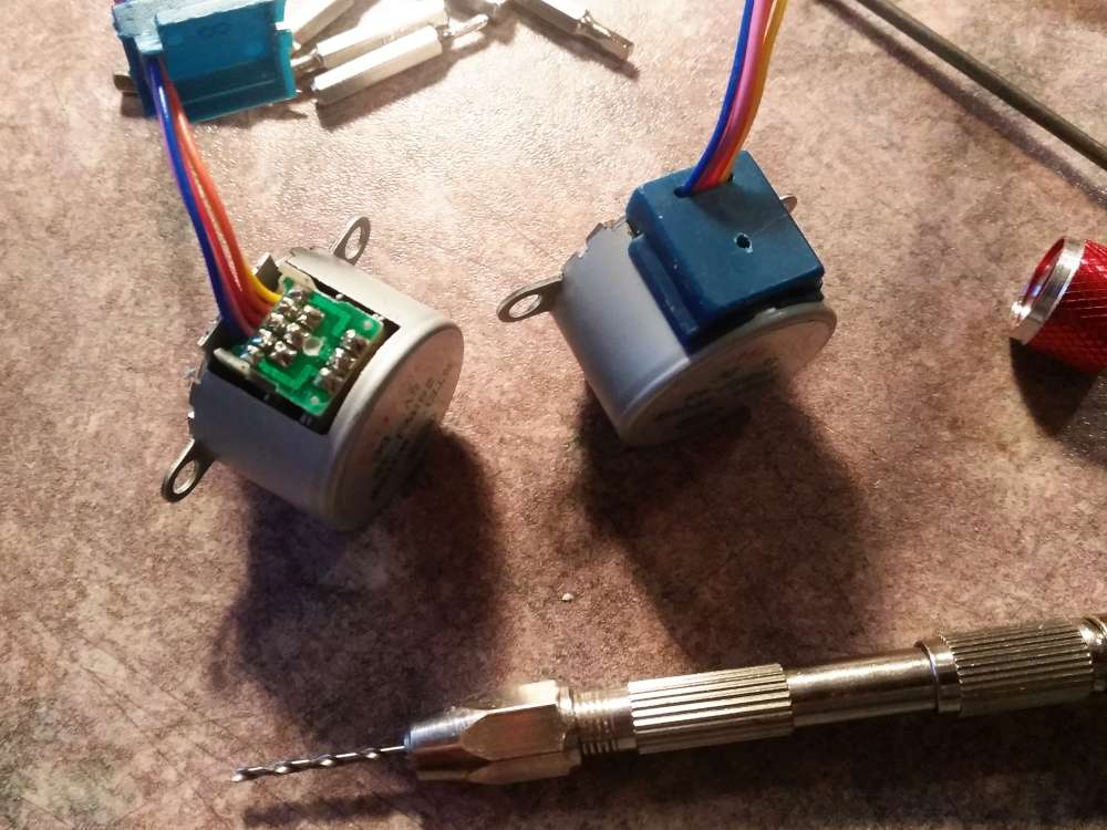
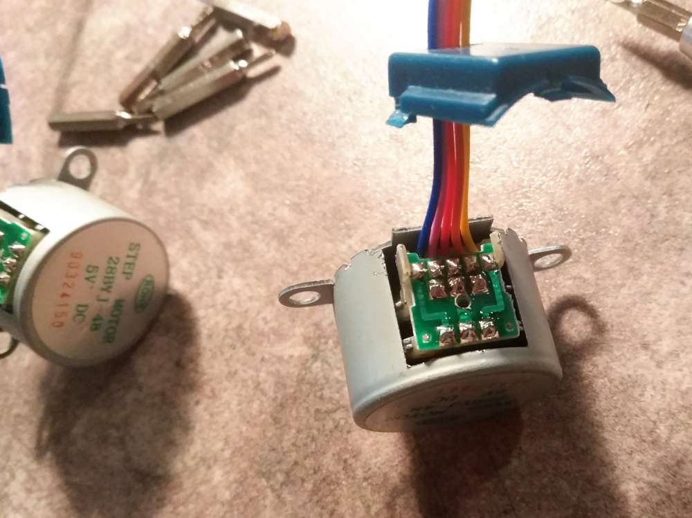
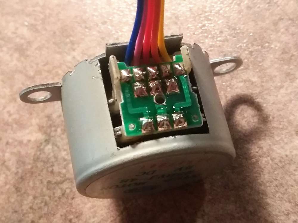
These are 5-wire motors. People sometimes remove the blue cover to cut the middle trace on the circuit board. This disables the “center-tap” in the motor winding converting it to a 4-wire motor. Doug Commons was telling me about his idea of drilling the trace out blind without opening the motor. It works like a charm. You can see the pictures below from my experiments. I’ll have you know I made my own 1″ pitch graph paper on my CNC machine for the pictures.

Here’s a quick video…
Steps to Drill the 28BYJ-48
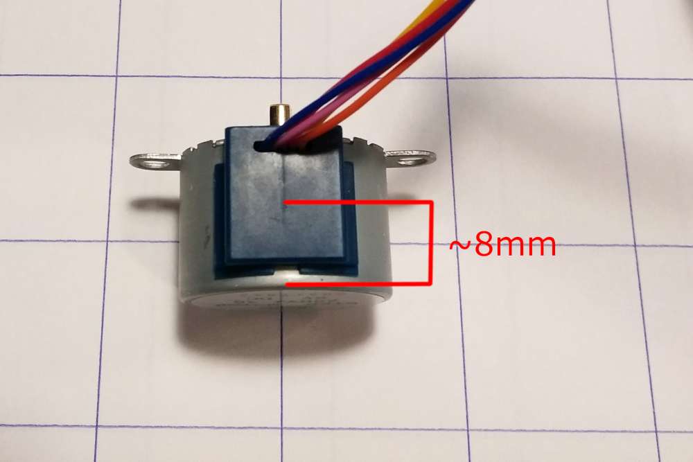
Mark the blue cover for drilling about 7.5 or 8mm from the label-face of the motor. Estimate the center of the blue cover from left to right and drill. I used a 1.58mm (0.0665″) drill but I think it would work well if it was larger. After you get through the blue cover and you are in contact with the circuit board verify the perpendicularity of the drill. Keep going till you’re through the board. You’re done.
I wonder if a jig would make this even easier. Doug and I may make up a jig design.
Wiring
On the circuit board the wiring is blue, pink, red, orange, yellow. That’s a nested configuration abcBA (where aA and bB are coils and c is the center-tap). It’s easy to check this with a meter. The little white jack they come with is wired differently however. It is abABc which is staggered with the center-tap on the end. I noticed the nema17 motors on my Arduino CNC Shield are wired abAB. So it’s just a matter of plugging them onto the shield making sure the red wire is off the edge and not plugged in (you’re plugging a 5 wire onto 4 wire and you just make sure the 5th wire isn’t plugged in).
The Rest of the Machine
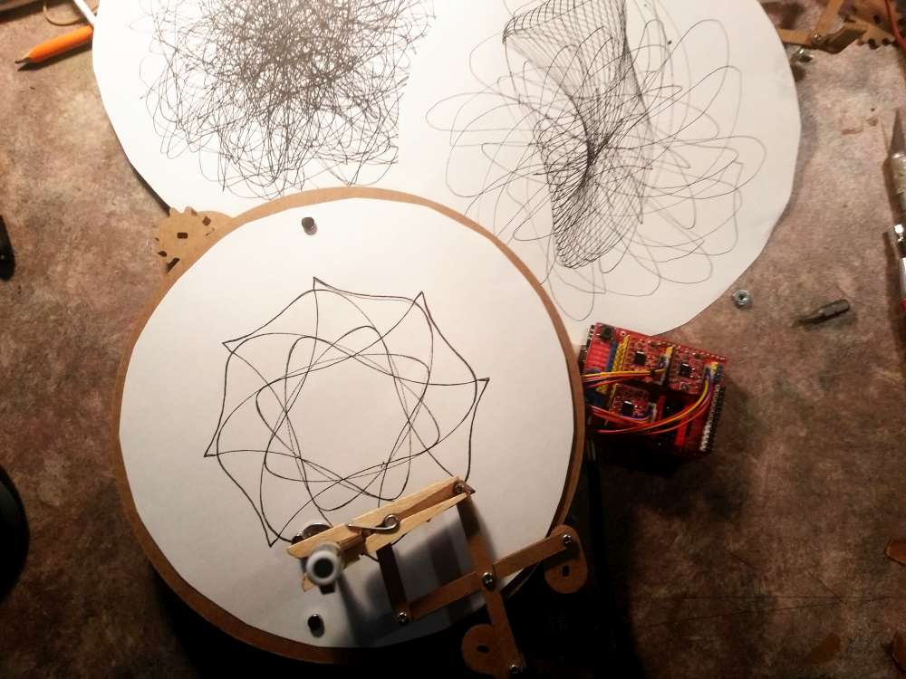
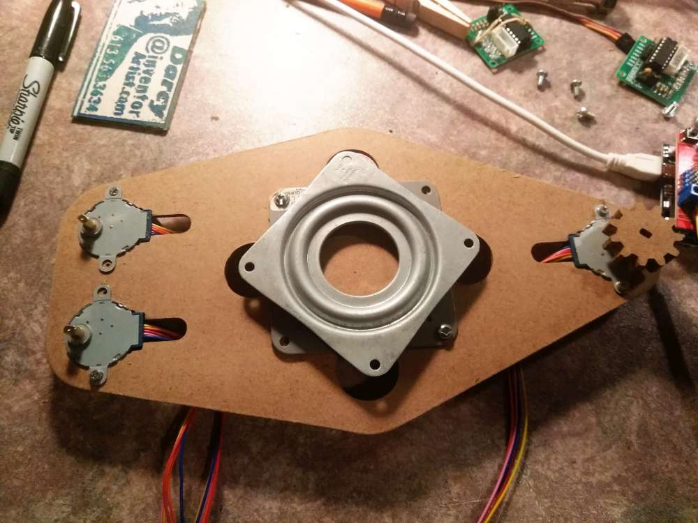
Now that we have 4-wire motors, I just plugged them onto a CNC Shield (ignoring the red wire as described above). I added three A4988 drivers and an Arduino Uno. I loaded GRBL onto the Arduino and let it simmer for 10 minutes. I then connected 12V to the GRBL board.
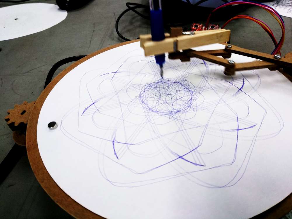
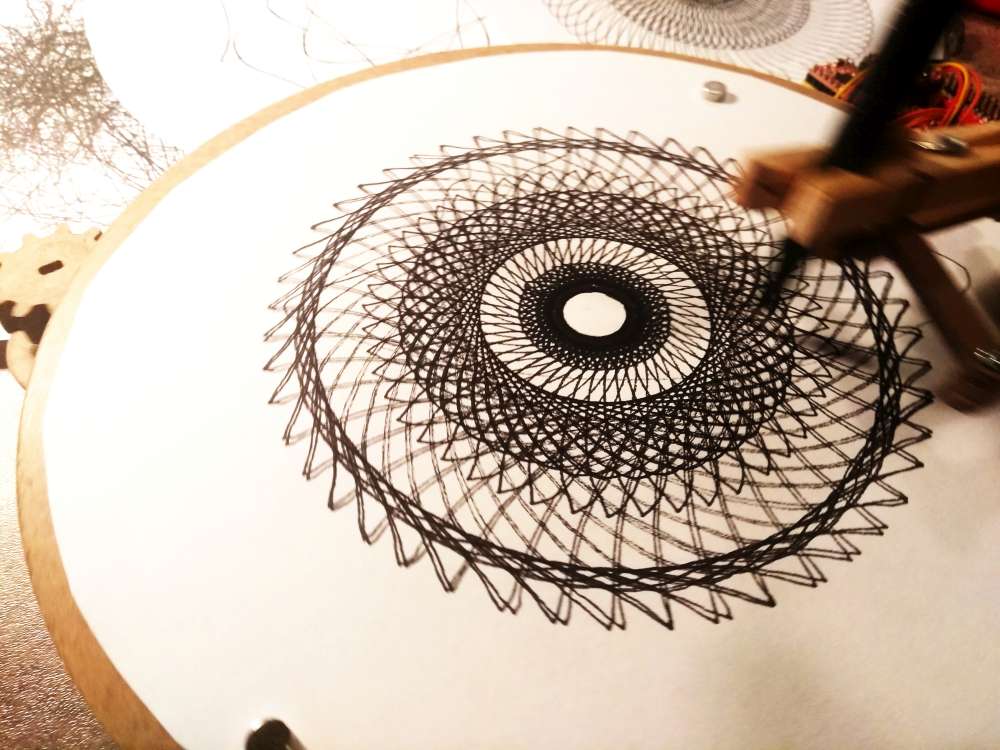
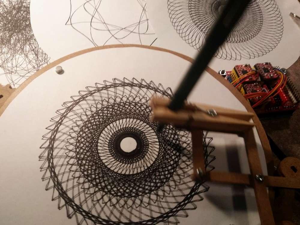
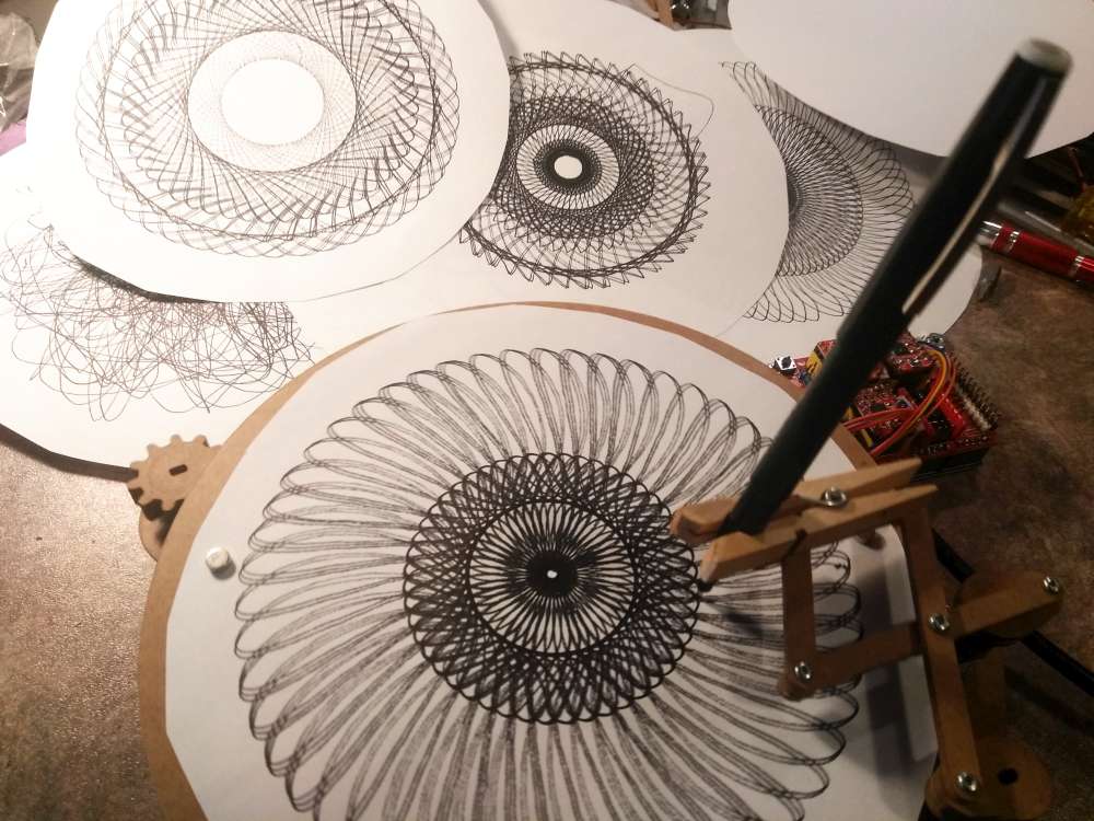
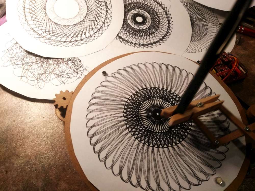
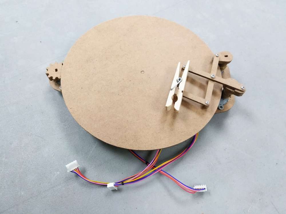
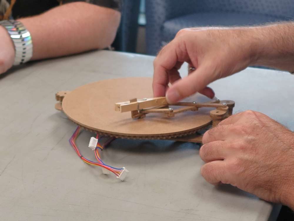
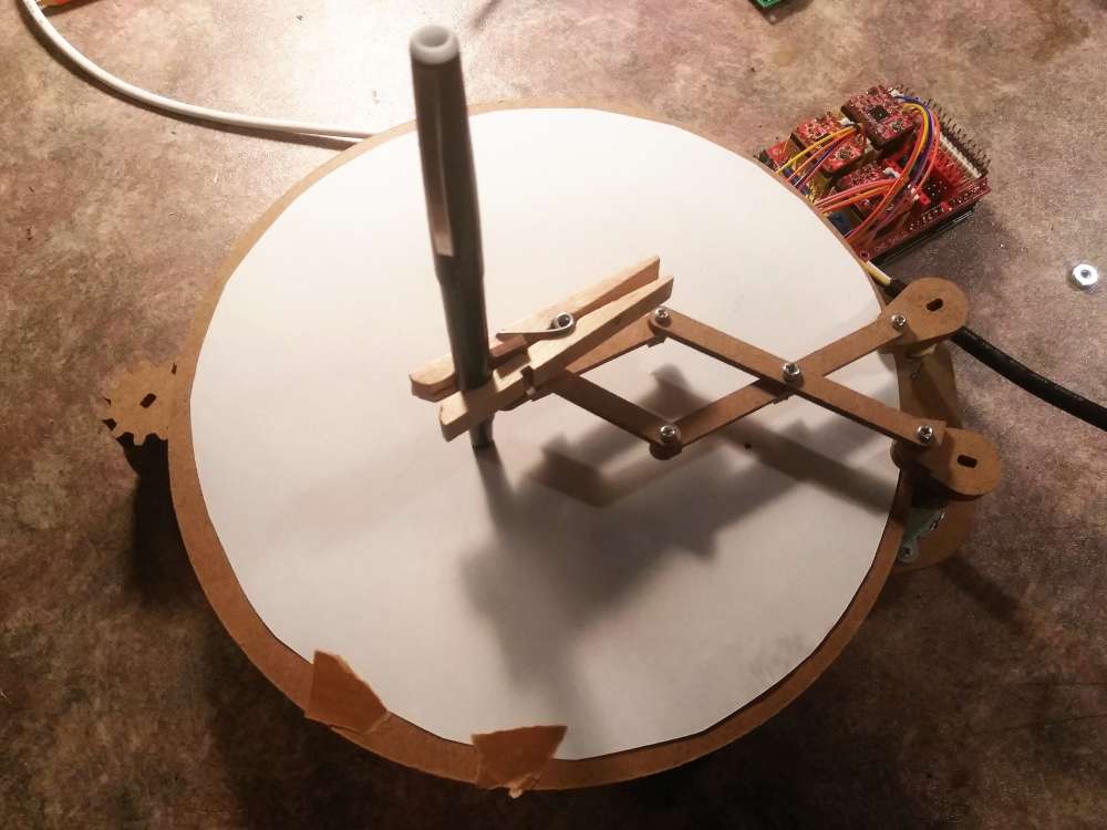
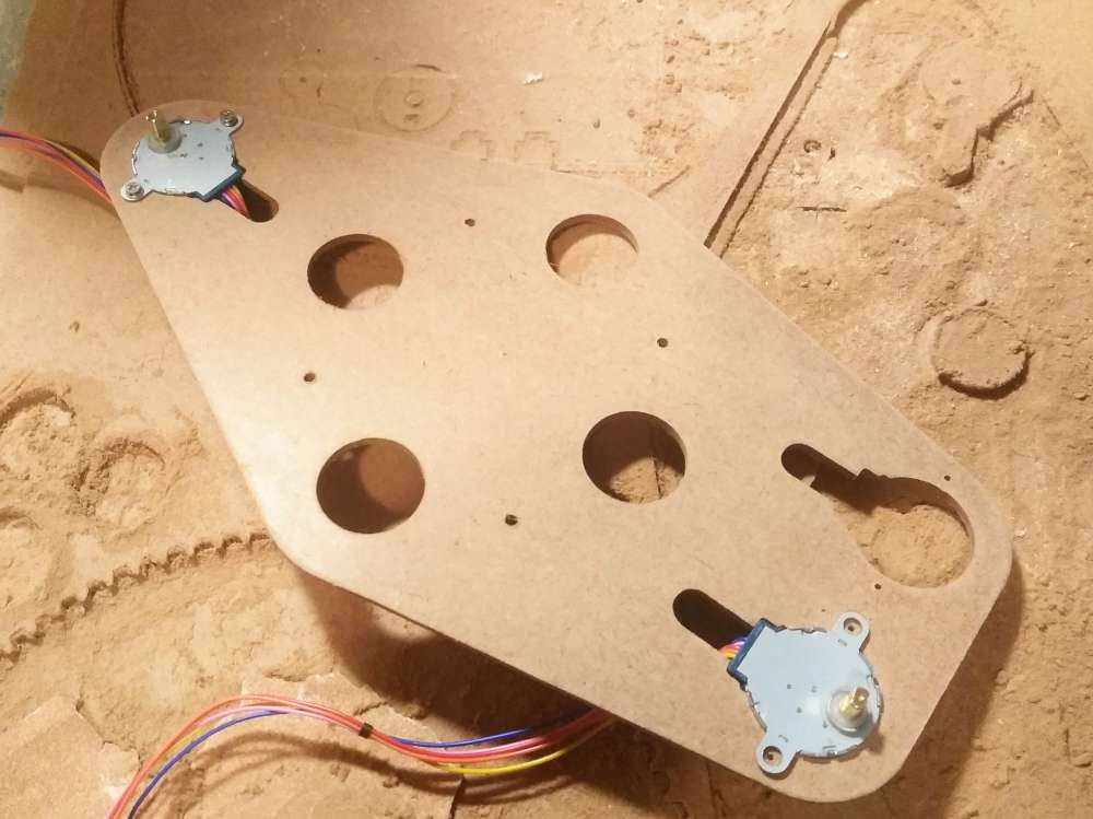
The mechanical of the machine is a 3″ lazy Susan bearing, some screws, a clothes pin, four rare-earth magnets and some hardboard. I made up the frame of the machine on my CNC machine.
I sent the g-code to the machine through a GRBL client: x5000y5000-z4980
This is so fun I’m not going to leave the house for at least a week.
Bill of materials:
I’m not endorsing these sellers, I just did a quick search so I could brag the cost of this machine to be under $20.
28BYJ-48 steppers: $3.60
controller Arduino CNC shield kit with A4988 Drivers: $9.90
bearing lazy suzan: $2.20
hardboard home depot: $2.74
screws: Out of disassembled junk
TOTAL: $18.44
Headless Code
I’ve been running the machine using GRBL with g-code (example above). This works really well.
I’ve started to develop a headless version. This can run without a laptop tethered to the CNC shield. Here is the Arduino code I’m working on. It can run on the Arduino with the CNC shield installed and conveniently access the stepper drivers.
It works except for some reason when I put in different values for the motors they still go at the same rate. Not sure why. Any ideas?
//Cycloid-O-Matic headless code
//
//Darcy@inventorArtist.com
//Project Page: http://inventorartist.com/cycloid-o-matic/
//
//I only have one pot on hand so try and control three
//motors with one pot.
//
//This uses the CNC shield but without GRBL.
//
//copyright Darcy Whyte, 2019

//User input
const int potPin = A0; //abort pin on CNC Sheild
int potValue = 0;
long userMode = 0;
unsigned long userLast = 0;
unsigned long userInterval = 100000;

//State visulaization
//const int seePin = A1; //analogWrite(seePin, map(potValue, 0, 1023, 700, 1023));

//Motor physical
const int xPin = 2; const int xDir = 5;
const int yPin = 3; const int yDir = 6;
const int zPin = 4; const int zDir = 7;
const int motorOn = 8; //enable steppers

//Motor logical
unsigned long xLast = 0; long xInterval = 0; int xState = 1;
unsigned long yLast = 0; long yInterval = 0; int yState = 1;
unsigned long zLast = 0; long zInterval = 0; int zState = 1;

void setup() {
  Serial.begin(9600); //debug
  pinMode(xPin, OUTPUT); pinMode(xDir, OUTPUT); //motors
  pinMode(yPin, OUTPUT); pinMode(yDir, OUTPUT);
  pinMode(zPin, OUTPUT); pinMode(zDir, OUTPUT);
  pinMode(motorOn, OUTPUT);
  digitalWrite(motorOn, LOW);
}

void loop() {
  unsigned long currentTime = micros();
  if (currentTime - userLast >= userInterval) {
    userLast = currentTime;
    potValue = analogRead(potPin); //Serial.println(potValue);
    userMode = map(potValue, 0, 1023, 0, 4);
    switch (userMode) {
      case 0:
        xInterval = 0; yInterval = 0; zInterval = 0;
        break;
      case 1:
        xInterval = 600; yInterval = 600; zInterval = 550;
        break;
      case 2:
        xInterval = 500; yInterval = 490; zInterval = 500;
        break;
      case 3:
        xInterval = 450; yInterval = 450; zInterval = 450;
        break;
      case 4:
        xInterval = 420; yInterval = 500; zInterval = 480;
        break;
    }
  }
  if ((xInterval != 0) && (currentTime - xLast >= xInterval)) {
    xLast = currentTime; xState = -xState;
    if (xState == 1) {
      digitalWrite(xPin, HIGH);
    } else {
      digitalWrite(xPin, LOW);
    }
  }
  if ((yInterval != 0) && (currentTime - yLast >= yInterval)) {
    yLast = currentTime; yState = -yState;
    if (yState == 1) {
      digitalWrite(yPin, HIGH);
    } else {
      digitalWrite(yPin, LOW);
    }
  }
  if ((zInterval != 0) && (currentTime - zLast >= zInterval)) {
    zLast = currentTime; zState = -zState;
    if (zState == 1) {
      digitalWrite(zPin, HIGH);
    } else {
      digitalWrite(zPin, LOW);
    }
  }
}
Related
This article was featured in hackaday!
Also in hackster.
Also IOTosphere.