Easy Wind DC Motor
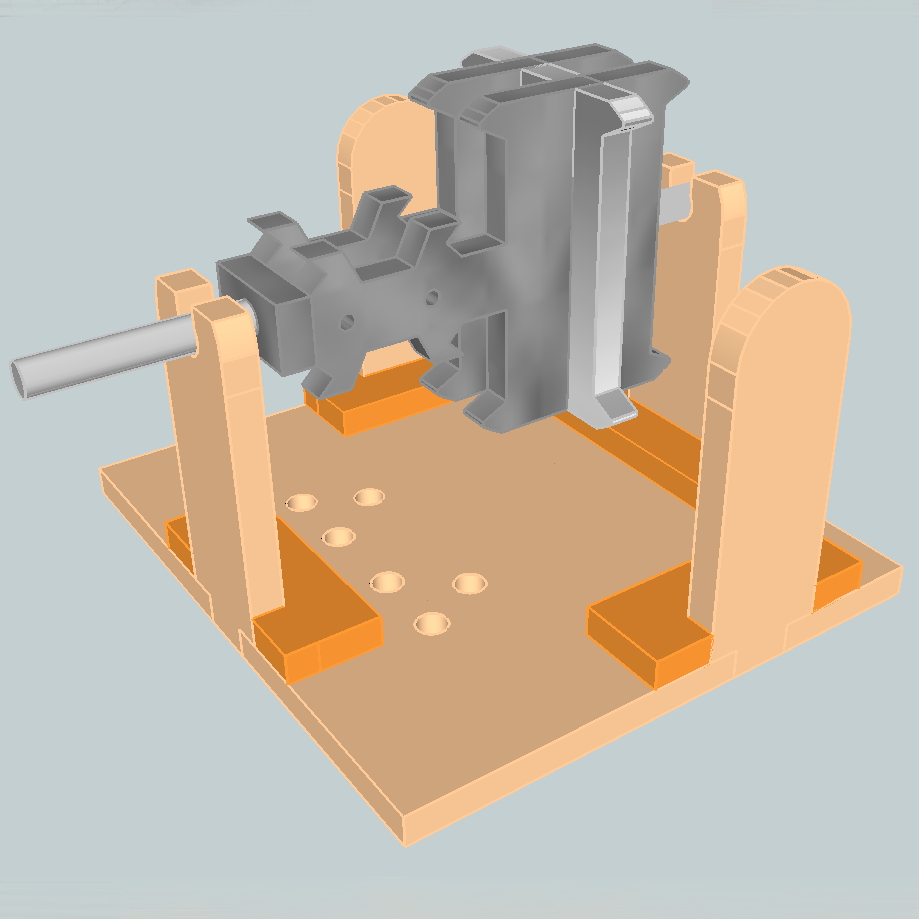 Here is the latest version of the DC Motor project.
Improvements over the last version are as follows.
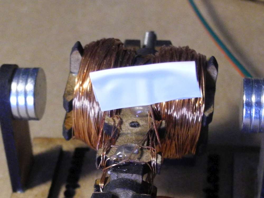
Commutator: This is a wound commutator that uses the same piece of wire as the armature. It’s very easy to wind since you don’t have to join wire to the commutator. You fasten the wire to a hole, wind a commutator, wind the armature poles, wind the other commutator and then fasten the remaining wire to a hole. It’s all one smooth action. Then you scrape the enamel on the commutator to expose the copper.
Armature Poles: I put more flanges on the armature and rounded them off so the magnets can be closer to the coils.
Shaft: I made some wooden nuts that will screw on to secure the armature to the shaft and help keep the armature in place. The commutator also has a hole for the shaft so is supported at two places so there’s no chance of wobble.
Brushes: I decided to go with a coil spring at the bottom to allow better tracking.
That’s the theory. Here it is in practice.
Building the Prototype
I decided to laser cut since I was at the ArtEngine Lab which doesn’t have a mill.
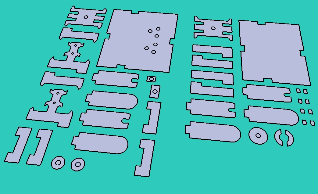

I’ve been enjoying how effortless it is to design using a computer, test fit parts then cut them out with CNC (either CNC Laser or CNC Mill). It really streamlines the process and you get great quality parts. I don’t know how I ever lived without CNC.
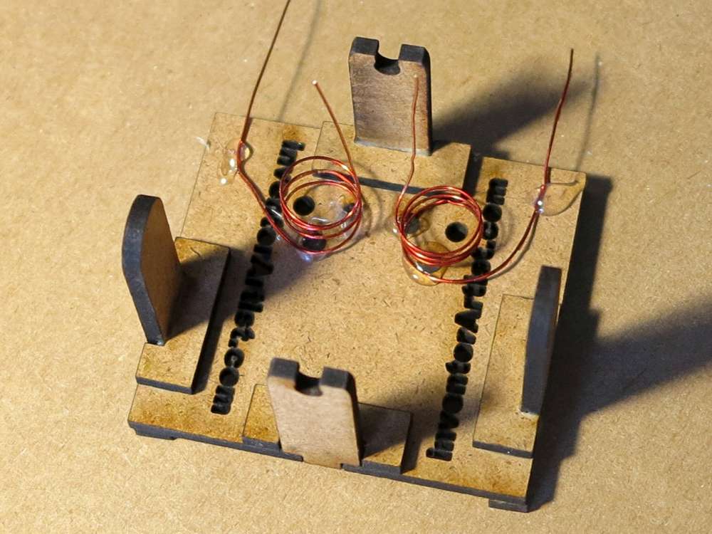
I glued the armature and base using wood glue. I suppose a glue gun could be used. I may try that for the next prototype. This only took a couple of minutes. It’s very satisfying when things just fit!


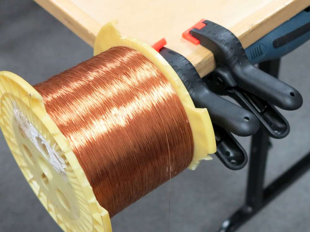
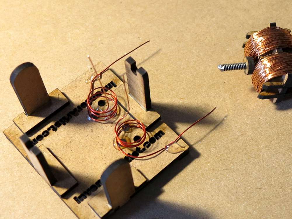
Then I wound the commutators and armature poles. Notice how I wound a little four leave clover for the commutator. It is very easy to do all in one step. Most of the time is just counting up the winds. The little clover leave didn’t work as well so I tried another winding pattern which worked.
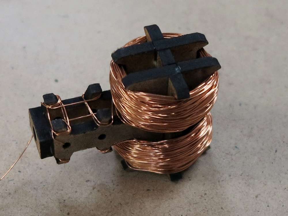
I then made the brushes and dropped them in place with a glue gun. The plan was to wind them into the holes I made but it was too hard without damaging the coil springs. I made the coils springs by winding around my thicker exacto handle.
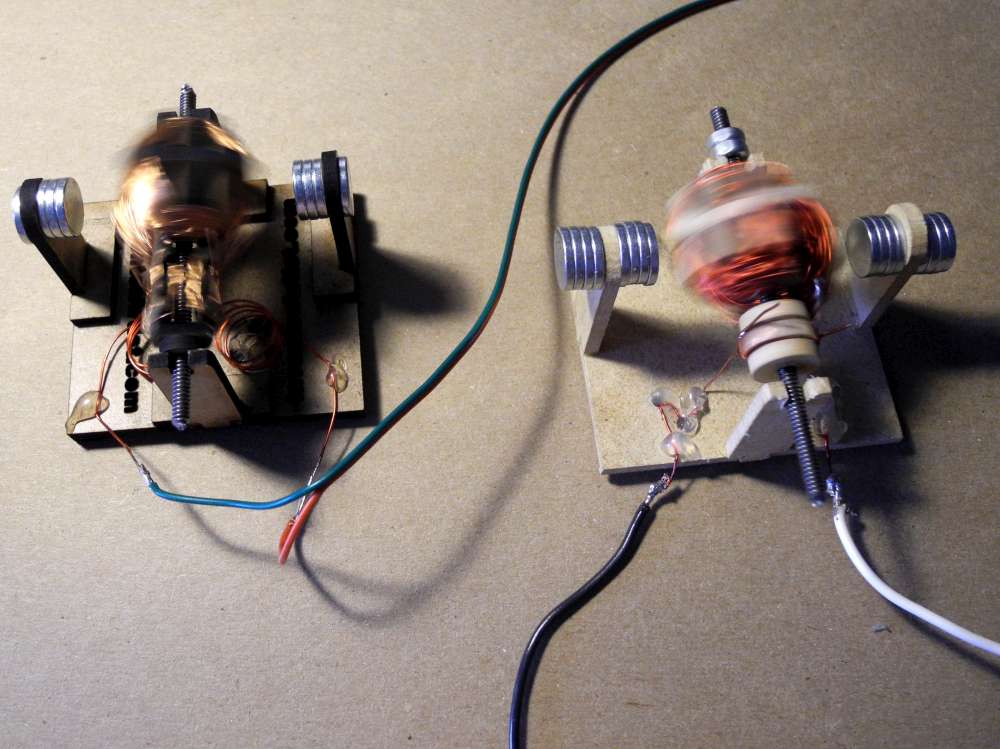
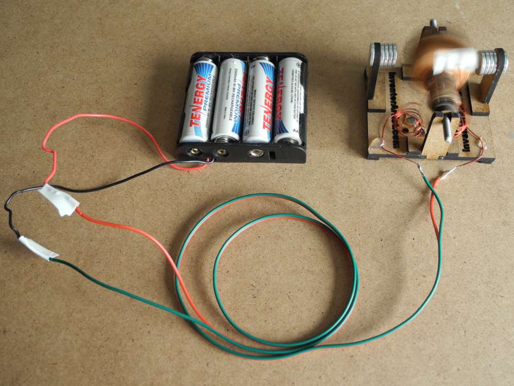
I then dropped the armature in, soldered some power leads and gave it a test run. Here it is running along side the previous version of this motor. It has a lot more torque and runs very quiet and smooth. Also the shaft clicks in place nicely and the laser surface seems to be very smooth and slippery to the 6-32 threaded rod I used for the shaft.
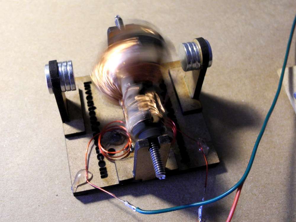
I added a piece of tape as a brush tensioner and got a lot more RPM. I’ll bring out my tachometer for the next test run. My lab supply showed the motor drawing around 200mA and 400mA at stall (that was at 9V). I’m pleased with that. So connected an AA NiMH to it. Ran fine. I put together a pack of 4 AA’s and it ran quite strongly. I let it go for 40m and there was no sign of drain on the batteries.
What next?
I was thinking of making it into a little car or have a twirling ballerina. Or a whirligig. What do you think would make this more fun?